Pages

Thursday, April 30, 2015

Wijnmaker APP

Many years ago I started winemaking and for winemaking you need to do calculations for gaining the right amount of alcohol in your wine. Alcohol is made by yeast that consumes sugar ansd makes alcohol from it. For measuring the right amount sugar in your juice Specific Gravity (SG) is used. During all these past years I develloped my own SG table which is now used by thousands of enthousiastic home winemakers.

You can find all information by browsing through my WIJNMAKER weblog by clicking here.

A few weeks ago I found a very easy programming method to make your own Android APPs. It is called App-Inventor and supported by the MIT. I wrote about it before in the web-log here. So after examining several source codes I realised indeed how easy it was to make your own APP for Android. So I started wondering what to make. Well that was easy to find. I know from the emails I get and the posts on winemaking forums how much difficulties hobby winemakers have with calculating how much sugar to add when they are winemaking. Acid calculations are also sometimes problematic. Well that is all past-time. Here comes the Wijnmaker APP !!! You can install it on your android phone or tablet. It will work on both. No wifi aquired or even a data bundle. The app completely works off-line.

I did not post this on the Android Play store (I might later on) and it is only in English. But hey it works and most winemakers that are present on the internet read English.

So how do you install it.

Step 1
Go to your Android settings and look at your safety settings (for Android 4 up) or Apps (for earlier Android versions) and make sure that installing apps from unknown sources is allowed.

Step 2
Scroll down to the end of this page and click on download at the name of the file Wijnmaker_uk.apk Off course you need to do that on your phone or tablet and not on a windows, mac or linux machine.

Step 2 A
You can download the app on your desktop computer but then you have to manually transfer it to your Android machine. You can do that easily by using cloud-based storage utilities like Copy or Google Drive. I demonstrated that in my weblog:
http://lucstechpage.weebly.com/blog/working-in-the-cloud

Step 3
Open your file browser from your apps (bestandsbeheer in Dutch) and go to the download folder on your SD card. There you will find the Wijnmaker_uk app. Click on it. Android than asks if you want to install it. Off course you want that !!!

Step 4
That's it. You can now put the App on your Android screen if you want. The app has its own unique icon that is familliar to the visitors of my weblog.

Some general thoughts.

First why no Desktop computer program.
Well that is easy. No winemaker with good sense puts a computer in his kitchen or winemaking room with all that water and sticky juices around. In no time accidents would happen. A tablet or phone is much more convenient.

Why didn't I put it on the Google Play store.
Well I am thinking about this. But, hey, these webpages are about technology so I presume you know how to install apps in Android.

You followed the abbove steps and don't understand anything about that.

Well then this is the wrong weblog for you. Search the net for information on installing android apps or find a friend who can help you.

Will there be an Iphone/Ipad version ??
Definitely !!! As soon as someone is donating me an Iphone and an Ipad I will be working on an Apple version. Not sooner as that. So if you want this App bad donate me enough money to buy these machines......... So show me the money ;)

Will you publish the sourcecode.
Well it is against all I stand for on these webpages and on my wijnmaker weblog but the answer is no. Why you ask. Well that is for safety reasons. I do not want anybody messing with the source code and altering the calculations that are in it. If that should happen and that person would spread the altered version around it could ruin wines made by hobbyists that would have downloaded the altered version.

Can I test the outcomes of the APP
Well sure you can. just go to my wijnmaker weblog and find some recipes. Look at the calculations done in those recipes and just fill the figures in, in the APP. That way you can check wether the outcomes of the calculations are the same.

Why is it free
I know. I know. I could have become multi-millionaire by selling this app on the Google playstore. But hey I am altruistic and a generally easy going guy. I never allowed advertisements on my wijnmaker.weblog and I do not do advertisements here. I am doing this for fun. It is not my job. I love open-source and open-hardware. I learn a lot every day. Having fun in making things is my reward.

And here it is:


Click here to

Download the

Wijnmaker APP


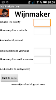
The app has 4 buttons. Each button takes you to a different screen with the mentioned calculations. Just experiment with it and see how easy it is to do your winemaking calculations.


Update: 16-05-2015
Winemaker APP was chosen as 

APP of the month may 2015 

by the MIT !!!


Saturday, April 18, 2015

Ledstrip Controlling 2


Ok so last times on this weblog we made a little detour. In a previous post I showed you how to cut the ledstrip and attach wires to the 12volt and RGB connections. Next I showed you how to control a ledstrip with switches. And then I showed you how to control a relay throught bluetooth with your Android Phone. Lets combine that and lets control the ledstrip with our Android Phone.

Ok so first we have the setup with the power transistors that are attached to the ledstrip just like we did last time. As you can see I am using the TIP 120 transistors again as they are much more powerfull as the BC547. And power is what we need to control a ledstrip.

.If you can not find the TIP 120 the TIP122 will do equally well 


But here the similarity ends. We want to control this with an Attiny85. So lets attach the Attiny pins to the ledstrip.


Now we do have a small problem. That is that we can not feed the Attiny85 with the 12 volts power supply from the ledstrip. So we need to bring the 12 volt down to 5 volts. I used a 7805 voltage regulator for that purpose. You can see that in the next layout:


So now there is only one thing left to do. The Attiny has to know what commands to send to the ledstrip and we are going to do that with the HC06 bluetooth module. Here is the final layout.


So here is the breadboard layout.


Some notes:
On the red strip on the side of the breadboard the + 12 volts will be attached
On the blue strip on the side of the breadboard the ground is attached.
On each middle pin of the transistor is the R, G or B wire attached from the ledstrip.

Check and check again especially the power lines. It would be a shame if you blew up your Attiny85 or the Bluetooth module or even the transistors.

So we now have the hardware complete. Now for the software.


Ok a bit about the code. Attiny85 digital pin 0 is Transmit (TxD) to the HC-06 module and pin digital pin1 is the Receive pin (RxD). The led strip is connected to digital pins 2,3 and 4.

The code:

if(blueToothSerial.available())

Tests constantly if a character is received. We just test for 1 character. With 1 character we can give the Attiny 62 commands !!
Hows that you say. Well we do have 26 letters (A-Z) and then 26 capitals (A-Z) and 10 figures (0-9).
62 commands should be sufficient for many many projects.......

So lets look at a part of the code:

else if(recvChar == '7') // wit
{
digitalWrite(led1, HIGH);
digitalWrite(led2, HIGH);
digitalWrite(led3, HIGH);
}


Ok as you can see this part tests if the figure 7 is received from the bluetooth module. If that is the case the Attiny85 will put a HIGH signal on the digital pins. This will send a signal to the RGB strip putting all leds ON which gives the color white.
Easy !!

So now for the Android part.
The code was just as in previous posts made in App-Inventor. You should really dive into App-Inventor as it is really easy to write apps in this environment. You can find App-Inventor here.

So I am not going to teach you how to program in app inventor but I am going to show you partially how this app is made.

First you determine the layout of the screen. For this app it looks like this:


Yep sorry it is in Dutch. Hey I am Dutch. So to translate it in English learn how to use App-Inventor. It is really worth it.

As you can see I defined 13 buttons. 12 Buttons for setting a colour on or off and 1 button for the Copyright announcement.

Copyright ???
Well not really. Off course this code is made by me and therefore I own the Copyright. However you are free to modify it to your own liking and needs. The code will be ready for downloading at the bottom of this text.

And lastly there is a Listpicker for selecting the Bluetooth device. In App-Inventor it looks like this:


And then we have the App-Inventor blocks (code). Look at them and see how easy it is to make an App. I can not emphasize this enough.


So how to use this App.

First click on the white button for choosing your bliuetooth device. Somewhere in the list (if there is a list) you will find the HC-06 module. Choose it and you will see that the blinking led will stop blinking and light up continuously. This indicates that the connection between your phone and the HC-06 has been established.

Now you can choose the individual colors red, blue and green and you will see the corresponding colors light up on the led-strip. Put them off with the corresponding black button.

Cyaan, Magenta, Yellow and White are combination colours. Yellow for instance is made by lightning up the red and the green leds. Magenta is a combination of red and blue and white is made by lightning all colors. So to put these colors Off you will need to switch off the individual colors by using the black texted buttons.
There is one special button with the name random. It is obvious what that does.

If you need more buttons or different functions you are welcome to add your own codeblocks.

OK for the code here we go. First the Arduino code. Next the App-Inventor codeblocks which you can import in App-Inventor and last but not least the ready to use Android APP.

So thats it. Till next time. Have fun.

rekais01attiny.ino


Ledstripcommander listing

Ledstrip commander APK

Friday, April 10, 2015

Relay Commander


Ok, this is going to be one lengthy entry. I am going to tell you how to switch the lights in your home (or sunshades, or whatever electrical applience) on or off with your Android phone using bluetooth.

So this involves electronics, programming the Attiny85 and making an Android App. All sounds complicated but is in reality much easier as it sounds.

In a previous entry I told you I ordered some HC06 bluetooth modules and I also told you that you could use them even with an Attiny85. So that is what we are going to do. I am also giving you the source code of the App Inventor program and the Arduino code so you can modify this for your own needs.

We are going to attach a bluetooth module to the Attiny85. This uses two of the pins of the Attiny85. So we still have 3 pins left. On these pins we are going to attach a relay.

Why a relay. Well that is obvious. The Attiny can not control 220 volts directly. The small tiny can just put out 5 volts at a very low current like 20 milivolts. And qwe want to control 220 volt 35 watt lamps or whatever.

So first I will tell you how to attach a relay to an Ayttiny85. Here are the schematics.

Ok in this picture you can see a resistor of 2.2k which is attached to the base of a BC547 transistor. At the other side of the resistor we will attach the Attiny85. The transistor will amplify the signal it receives from the tiny. The amplified signal will then activate the coil of the relay which will then activate and put on the ;light or whatever. Please note the diode which is connected parallel on the relay coil but in the false direction. This will prevent any current floating back into the circuit and ruining your transistor or Attiny85.

Testing the circuit so far is easy. just connect the polarity tester which is described on this webpage (click here) to where the relay should be connected and both leds should be off or shine faint. Now when you attach the loose end from the resistor to the 5 volts power supply one of the leds should light up. If that is the case youre ok. If not check the wiring again.

Next step is to connect the Attiny85 and the HC06 bluetooth module.


As you can see pin 7 of the Arduino is attached to the resistor. This will actually switch the relay on and off. Pin 5 and 6 are attached to the bluetooth module. I will give you a breadboard setup of this circuit.


For clarity I have left out the 5 volt power line and the ground line to the Attiny85 and the HC06 module as that speaks for itself.

So this part is ready now the software for the Attiny.

To have the Attiny85 talk to the bluetooth module we need to include a library in our sourcecode being the SoftwareSerial library which is standard included in the Arduino IDE.

So the code looks like this:


The code is simple. it polls the serial connection for a character and then on receiving the character it decides to put the Arduino pin High or Low. There are a lot of comments in to make life easier for you. I decided to only put the code for one relay in. Expanding to 2 or 3 relays should be easy for you.

Next step is to make an app in Mit's App Inventor. I wrote about app inventor before on this blog and you can find that entry here (click).

The code is very simple and self explanatory.


For those amongst you who have no experience with app-inventor maybe a short explanation will help you.
First the Listpicker command helps us to make a bluetooth connection. Next you see the buttons which are present on the screen. There are 6 buttons. Each relay has 2 buttons on for setting the relay on and one for putting it off. Well the code for that is easy. For relay 1 we send a 0 or a 1 to the Attiny over bluetooth. For relay 2 we send a 2 or 3 and for the last relay we will send 4 or 5. That all that is to it.

On your Android phone or tablet it will look like this.


To install this app go to the bottom of this screen and click on the download button at the apk file. Do this off course on your phone or tablet. You can do it on your PC to. Then you will have to transfer it to the phone or tablet manually. The apk file will be in the doewnload folder of your phone/tablet. Now click on it and Android asks if it has to be installed. Off course it has to. Then activate Bluetooth on the phone. Next start the app and first click on the Pick your bluetooth adapter text. You will see a list off blutooth devices and the HC06 will be one of them. Click on that and when the connection has been established the light on the HC06 will steady.

Detailed information on installing the app can be found in this story where we do something similar.

Now you can use the buttons on the phone to set the relay's on or off.

That's it. Easy. piece of cake.

Just a warning.
Connecting a relay to your home appliences involves high voltage and current. Please be carefull and only do this if you have experience with electricity. I do not take any responsibility for any mishaps, fires or electrocutions that may happen to you. You do this on your own risk.

Rests only one thing: the source files for Arduino and Mit App inventor and the Android APK file.

So till next time have fun.

Ohh and for those amongst you that are curious about the colours of the burrons. You know where this will lead to don't you........ In the end we are going to control a led strip with our phone.


Relais01attiny.ino


Relaycommander.aia


Relaycommander.apk

Saturday, April 4, 2015

Ledstrip controlling 1

So in the previous blog entry I showed you how to cut off parts of a ledstrip and solder wires to these parts (click). The wires were prepared so they could be connected on a breadboard using this technique (click).

You can see the soldered wires here.


And the attachment for the breadboard in the next picture

But what now ??? The purpose is to command the ledstrip with an arduino or even better an Attiny.

Well there are some issues with this. First the ledstrip works on 12 volts and the Arduino and the Tiny work on 5 volts.
And second there is no way an Arduino or an Attiny can supply enough power to control all the leds in a ledstrip.

So we have to use some power transistors to do the heavy work for the Arduino.

I am going to use the Tip 120 for this. Actually you can use the Tip 121 or Tip 122 equally well for this. They can work at higher voltages but are equally suitable for this purpose.


The Tip 120 is a power transistor capable of delivering 2 Amps at 60 Volts. That is a lot of power and more as sufficient for controlling the ledstrip. So we are going to use 3 of them the command the R, G and B leds in our strip. This is the schematic setup.


As you can see for testing purposes I put a switch on the base connected to a 5 volts power supply. The switch emulates an Arduino pin witch is on High. The collector is connected to one of the R, R or B leads from the ledstrip and the emitter just connects to the ground.

Now by pushing a switch you will get the strip displaying the accompaning colour. By pushing multiple switches you will get combination colours. For example pushing all 3 buttons turns the strip white. By pushing the R and G button you will get a yellowish light and by pressing the R and B buttons at the same time you will get a Cyanish colour.

Acrually I did not use switches. I just put 3 breadboard wires into the +5 volt and attached each of them to the loose end of the resistor. I am a lazy maker and this worker equally well as attachingb switches.......

Ok here is my somewhat chaotic breadboard setup.


And here is the breadboard as Fritzing sees it, which should make things more clear.


Next stop: Arduino attachment. Till then have fun.