For an index to all my stories click this text
Lately I have been playing with the ESP32cam. A small board containing an ESP32, a SD card slot and a camera !! If you haven't heard about it by now you have been living under a rock. The picture and video quality is all in all very satisfying for a board of this price. For around 6 dollar from your favorite chinese supplyer you will get a complete IP-camera.
I will not go into details about installing the software on this board because there are enough tutorials on the internet about his. Well.......unless you want me to write one that is.

The problem with this board however is that it lacks a USB port. So to program it you will need a FTDI (USB to serial converter). These can be had for a few dollar and can also be used to program Attiny microcontrollers and ESP-01's. Long time ago I published an ESP-01 programming board which also uses an FTDI. You can read that story here: https://lucstechblog.blogspot.com/2019/11/esp-01-programming-board-new.html
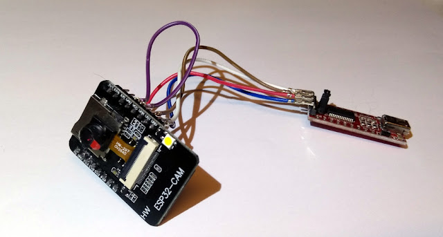
Attaching the ESP32cam to the FTDI is easy but involves several wires to be attached. It looks like a bunch of spaghetti.
So to simplify things I decided to build a small programming board for the ESP32cam. I did it on stripboard so you can easily reproduce it.
Schematics.
This is how the board is wired.
At the bottom you can see a USB connector of which only the VCC and GND are connected.
This can be used only as a USB power supply when the FTDI is not connected. You can only program the ESP32cam with the FTDI connector.
At the left there is a header in which we can place the FTDI converter.
Please note thatb the GND and VCC of the FTDI and USB connector are connected to the ESP32 and to eachother. So NEVER connect an USB cable to your computer and at the same time an FTDI converter to your computer. Als DO NOT connect a USB power supply and the FTDI together. This might damage your computer beyond repair.
At the left on the top you can see a switch. When closed it connects GND to IO0 and then you can program the ESP32cam board. If the switch is open the board can be used. A bit like the boot switch on a ESP32 Devkit Board.
BEWARE
There are several different FTDI converters available. The one displayed here has 6 pins. I also have a 5 pin version. These are not compatible !!! So when using this schematic make sure you adjust it for the pin-layout of the FTDI you are using.
Breadboard
After looking at the schematics you can see that the stripboard layout is simple.
Again: your FTDI might have a different pin layout so beware of that.
At the bottom is the USB connector of which only VCC and GND are connected. At the top is the FTDI header. As you can see the lines of the stripboard have been cut in the middle so the FTDI and USB are not connected. The only line that is intact is the line at the left which is the GND.
On the right side there is a header for the ESP32cam board. Here also the lines in the middle are cut so the top pins of the ESP32cam do not connect to the lower pins.
VCC is connected to the ESP32cam on the right side at the bottom and on the FTDI pin and the USB connector.
GND is connected to the top left pin of the ESP32cam and also to the FTDI and the USB connector.
At the top right side there is the switch, it is connected to GND and IO0.
And then there are 2 wires that connect the TX and RX lines from the FTDI to the ESP32cam. 
Here you can see the stripboard when the ESP32cam module is mounted on its headers.
Real life
Just put the FTDI in its header, put the switch in connect state and you can program the ESP32cam.
After programing slide the switch back to the open state and remove the FTDI. You can then plug in a USB power supply or powerbank and look at the pictures on the ESP's website.
As you can see I put a small folded piece of paper beneath the USB connector so the pins are not bending all the time and stressing the print. For making it last I will put some hot-glue beneath the USB connector.
I am glad I build this board. Programming the ESP32cam is now a piece of cake. just slide it into the headers, program it, get it out and start using it.
Till next time
have fun
Luc Volders


