
Imagine getting home from your work. At opening the door some lights will automatically go on and the thermostat is being set to a comfortable 20 degrees. This not a view from the future but something we can build right now using Domoticz and the ESP8266.

My goal is to have at one time my complete house automated. To achieve this I want to make several long term tests. At this moment all the sensors and switches are controlled by Domoticz. I have written several stories about connecting an ESP8266 to Domoticz. Here is the list so far :
- ESP8266 sending data to Domoticz
A story that describes how to set switches on and off and send temperature data to Domoticz using ESP-Basic
- Sending data from ESP to Domoticz to set a lamp on or off written in Arduino IDE
- Sending data from ESP to Domoticz part II to send temperature data to Domoticz written in Arduino IDE
- Sending data from ESP8266 to Domoticz part III building a webpage that has buttons and temperature value and sends that data to Domoticz. Written in Arduino IDE
This is all fun. The programs show how to control lamps and switches in Domoticz and everything is commanded from your phone or computer. But there is not a lot of automation going on.
Geofencing
Let me explain what geofencing is.

How can we use this veirtual fence. Well, remember ping ????
Ping.
In may 2019 I wrote a story about Ping on this weblog: http://lucstechblog.blogspot.com/2019/05/ping-ping-anybody-home.html
The story demonstrated how an ESP8266 tested IP numbers of devices to see if they where operational and/or present. The program 'pinged' the IP number of your phone. If the phone was connected to your router a led would be set on, or a notification was put on a webpage.
What we are going to do
What we are going to do in this story is to Ping our phone and depending on our presence send a command to Domoticz. The command will set a switch on or off in Domoticz. That switch will be a reference for a script in Domoticz that will automatically set lights on or off depending on the value of the reference switch.
So in the end when we reach our home the lights will go on automatically. And when we leave they will be put out automatically. You can expand this by setting the thermostat to a certain temperature, starting the coffee machine and open the garage door automatically just to name a few options.
What is needed to make this project work
To get this to work you will need a full working Domoticz setup. Domoticz is a house automation system which is free and Open Source. Domoticz runs on a Raspberry (starting at Raspberry 2). To control your Coco (ClickOnClickOff or KlikAanKlikUit) lamps or other cheap 433Mhz lamps you will need a RFlink. This can be build easily by yourself. However a set of Ikea lamps with a bridge or a Philips Hue setup with a bridge can also be used. And you can make your own smart-lamps with an ESP8266 and connect that with Domoticz.
You can find the Domoticz website here:
https://www.domoticz.com/
The RFLINK website can be found here
http://www.rflink.nl/blog2/
Next to the Domoticz setup you will need an ESP8266. Even the humble ESP8266-01 can be used for this project. Indeed it is the module I am going to use. You can however replace it with any ESP8266 model like the NodeMCU or Wemos D1.
Programming is done in the Arduino IDE (C++).
Hardware setup.
Well not much to it. Just use any ESP8266 module with a power source. You can use a NodeMCU or Wemos D1 with an USB power adapter. I used an ESP-01 with a programming board and an USB power adapter.
Domoticz setup.
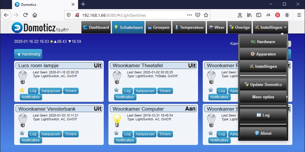
You will need at least one lamp attached to Domoticz. As you can see I have multiple lamps attached in my system.

The first thing we need to do is to add a new switch to Domoticz.

As you can see I already have a Virtual Switch called "Virtueel 1". This is my thermometer which I described in an earlier story which you can re-read here http://lucstechblog.blogspot.com/2020/01/sending-data-from-esp-to-domoticz-part.html We will need to add another virtual switch. Simply call it "Virtueel 2". The type of the Switch is dummy. Set the Timeout to "Not Active". And add the switch.

The new switch will appear in the list. Click on it and then click on "make virtual sensors".

Give the switch a name. I gave it the name "Is Luc Aanwezig" meaning "Is Luc present". And choose as type: Switch. Press OK.
Switch over to the Devices Menu in the Settings (right most tab).

Using the button at the top on the left I chose to display only active (Gebruikt) devices so the list is short.
The second device is the "Virtueel2" device which is the new created switch. Note the IDX in the second column. In this example it is 8500. Remember this as we will need it in the ESP8266 program. No need to write it down as you can come back to this menu anytime.


Change the switches icon from a lamp to the Phone Icon. And leave the rest of the settings unaltered. Chose "Opslaan" which will be "Save" in the English version.

The program will automatically jumpo back to the switches tab and you can see that the icon of the last switch has altered in a mobile phone just like we wanted. Now the switch is really representing what it means.
Pressing the little star on the left side of the switch will put it on your dashboard.

Here you can see my Dashboard with my mancave lamp and my phone switch. The screen of the phone in the switch will be black when it is off and coloured when it is on.
Find Domoticz and your Phone's IP Adress
Next step is to find Domoticz and your Phone's IP adress. Maybe you remember these from previous projects. If you dont you can find them in your router. Open the webpage from your router and look in the manual where to find IP adresses of connected devices.

As you can see in my router the Phone has IP adress 192.168.1.67 We will need that IP adress in the ESP8266 program.
Use the same way to get Domoticz IP adress. In my case that is 192.168.1.66
Domoticz API
On the Domoticz website we can find all API calls that we can use to control Domoticz externally. You can find that page here: https://www.domoticz.com/wiki/Domoticz_API/JSON_URL's
Chapter 3.2 tells us how to turn a switch on or off. The Api call for turning a switch on is:
/json.htm?type=command¶m=switchlight&idx=99&switchcmd=On
And for turning the switch Off the call is:
/json.htm?type=command¶m=switchlight&idx=99&switchcmd=Off
We have to translate that info Arduino code, which is not all to difficult. You will have to fill in the IDX which you found in Domoticz. In the above lines it is 99. In my example it was 8500. You can find it in the Domoticz settings in the devices section as described above.
ESP8266 program
As usual on my weblog I'll give you the full program first and then describe the most important parts.
/*
* Anybody Home ???
* This program tests an IP number. If that number is active
* a command is send to Domoticz which sets a switch on.
* This switch will in Domoticz be used as a reference for
* someone being present or not. Domoticz will then act on that.
* Written by Luc Volders
*/
#include <ESP8266WiFi.h>
#include <ESP8266Ping.h>
#include <ESP8266HTTPClient.h>
const char* ssid = "XXXXXXXXXXXXXXX";
const char* password = "YYYYYYYYYYYYYY";
const IPAddress Lucsphone(192, 168, 1, 67);
const char* host = "192.168.1.66";
const int port = 8080;
HTTPClient http;
int present = 0;
void setup()
{
Serial.begin(115200);
delay(200);
WiFi.begin(ssid, password);
while (WiFi.status() != WL_CONNECTED)
{
Serial.print("-o");
delay(100);
}
Serial.println("-");
}
void loop()
{
String url = "/json.htm?type=command¶m=switchlight&idx=";
if(Ping.ping(Lucsphone) && present == 0)
{
url += String(8500);
url += "&switchcmd=On";
Serial.println("on");
Serial.println(url);
sendToDomoticz(url);
present = 1;
}
else if(!Ping.ping(Lucsphone) && present == 1)
{
url += String(8500);
url += "&switchcmd=Off";
Serial.println("off");
Serial.println(url);
sendToDomoticz(url);
present = 0;
}
delay(15000);
}
void sendToDomoticz(String url){
Serial.print("Connecting to ");
Serial.println(host);
Serial.print("Requesting URL: ");
Serial.println(url);
http.begin(host,port,url);
int httpCode = http.GET();
if (httpCode) {
if (httpCode == 200) {
String payload = http.getString();
Serial.println("Domoticz response ");
Serial.println(payload);
}
}
Serial.println("closing connection");
http.end();
}
I will explain the program in detail.
#include <ESP8266WiFi.h>
#include <ESP8266Ping.h>
#include <ESP8266HTTPClient.h>
This is obvious. The required libraries are loaded. They should all be available in the Araduino IDE. If you did not build the project I described about the PING function it is time to re-read that story now and install the PING library. You can find the story here:
https://lucstechblog.blogspot.com/2019/05/ping-ping-anybody-home.html
If you just need to install the ESP8266 Ping library you can find it here:
https://github.com/dancol90/ESP8266Ping
const char* ssid = "XXXXXXXXXXXXXXXXXX";
const char* password = "YYYYYYYYYYYYYYYYYYY";

const IPAddress Lucsphone(192, 168, 1, 67);
Fill in your own Routers credentials at the XXXXXXX's and YYYYYYYYYY's. And fill in your phone's IP adress which you have looked up in your router as described above.
const char* host = "192.168.1.66";
const int   port = 8080;
Replace the host IP number by the number that Domoticz has in your router. The port is always 8080.
The setup has no magic in it. A variable with the name present is defined. Next the Serial Monitor is activated and the display shows a line being printed as lomg as the ESP8266 is not connected to the router. Nothing special here
String url = "/json.htm?type=command¶m=switchlight&idx=";
The loop starts with putting the first part of the Domoticz API call in a string with the name url.
    if(Ping.ping(Lucsphone) && present == 0)
    {
        url += String(8500);
        url += "&switchcmd=On";
        Serial.println("on");
        Serial.println(url);
        sendToDomoticz(url);
        present = 1;
    }
The PING library is executed with the IP adress of your mobile phone. If the PING part is true AND the present variable is 0 then the switch is off and should be set ON.
The IDX and the command ON are added to the url and printed in the Serial Monitor as a visual check. Then the sendToDomoticz(url); routine is called and the present variable is set to 1.
At the next test, after 15 seconds determined by the delay(15000) command, the Ping will be true and the present variable will be 1 and therefore the command will not be executed again.
    else if(!Ping.ping(Lucsphone) && present == 1)
    {
        url += String(8500);
        url += "&switchcmd=Off";
        Serial.println("off");
        Serial.println(url);
        sendToDomoticz(url);
        present = 0;
    }
This does the opposite. If PING is not true (!Ping) you will be out. So if present is 1 the switch is on and should be set off.
delay(15000);
The delay makes sure that the loop is executed once every 15 seconds. Adjust this tou your own needs. In my case it takes about 15 seconds to open my front door, put my coat in the closet and walk to my mancave. By then the lamp will be on. Your mileage may vary.
void sendToDomoticz(String url){
  Serial.print("Connecting to ");
  Serial.println(host);
  Serial.print("Requesting URL: ");
  Serial.println(url);
  http.begin(host,port,url);
  int httpCode = http.GET();
    if (httpCode) {
      if (httpCode == 200) {
        String payload = http.getString();
        Serial.println("Domoticz response ");
        Serial.println(payload);
      }
    }
  Serial.println("closing connection");
  http.end();
}
This is the routine that sends the url which is build in the loop to Domoticz by http commands. The serial port prints Domoticz IP adress and the url string which was build in the loop. Next using the host and port variables the url is send to Domoticz which switches the lamp ON or OFF. Domoticz sends an acknowledgement back and that is printed in the Serial Monitor.
Thats all.
Upload the program to the ESP8266 and reset the ESP. In the serial monitor you can see that the ESP8266 contacts the router and then the program starts pinging your phone.
First test
This is a simple test to see if everything in Domoticz works as expected.
Get your phone and activate wifi.

The Domoticz switch should be ON or set ON which is indicated by the blue screen of the Icon.
Now turn your Phone's wifi off.

In a few seconds the icon will change in a black screen.
Now we know that the new build switch works and reacts to the wifi settings in our phone. Cool !!!
So now we have a switch in Domoticz that will be set ON as soon as we enter our home and have the wifi in our phone activated. As soon as we leave out home the connection from the phone to the router will be lost and the switch will be set off.
Cool !!! Great !!!
But hey wait. We want the lamp in the mancave to react. Or to set a thermostat or open and close the garagedoor electrically or........ Thats right. Move on to the next step.
Automating Domoticz
We now have a working switch in Domoticz that reacts on our presence. The next step is to use that switch as a trigger to have Domoticz automate things for us.
In my example I have a lamp in my mancave which I want to turn on automatically when I enter my home, and turn off when I leave.

In Domoticz got to the Settings tab (on the right side), choose more options and happenings. In Dutch it is called "Meer opties" and "Gebeurtenissen".

We are presented with an empty screen in which we can graphically program Domoticz to automate functions. This way of programming is called Blockly in Domoticz and is a bit like Mit's App Inventor for building programs for your Android Phone.
You can build all kinds of routines. This example we make a routine which is called "presence". Fill this name in at the top right line where it says "Event name"

At the control section on the left choose the lower IF-DO block and drag it to the main screen.

Click on the blue gear and add the else-if block to the if block by dragging it to the if block.


Over at the Devices choose "Is Luc Aanwezig" and put that in the comperator. Then move back to the Logic section and Drag "ON" into the comperator. Put the block into the IF section.
Back to the Logic section and choose another comparation.
From the devices section add "Lucs Room lampje" and from the Logic section add "ON".

The first IF block should now look as the above picture. This translates as:
If "Is Luc Aanwezig" is "On"
Do set "Lucs room lampje" to "On"
Now build the Off block likewise.

Your complete program should now look as above.
On the right side in the screen set the event to Active and save it.
That's it.
All Done.
Everything should work now as planned. If you put the Wifi on your phone OFF the ESP will notice and send command to Domoticz to set the switch Off and that triggers the program to set the lamp off. When you set the wifi on again the route will be reversed and the lamp will go on.
Why the switch in Domoticz
In a previous story on this weblog you have seen how to set the lamp in Domoticz direct on or off. No intermediate switch needed. So why build such a switch in Domoticz.
Well this way you can alter the automation process in Domoticz to your liking. You can expand the if-else to have multiple lamps going on and off, switch fans on or off, set a temperature in your thermostat and everything else you can imagine with Domoticz.
It is also possible to use a timestamp in Domoticz. That way the lamp will not go on during day-time. Just use your imagination.
If we would set these things from within the ESP you would have to re-program the ESP each time you wanted a change. Re-programming Domoticz is much easier.
ESP expansion
In this example we test for the presence of one phone. You can easily alter the ESP8266 program to test for multiple phones like those of your partner and kids etc. You would then add multiple switches in Domoticz and have it react different on the presence of your partner or kids or whatever.
Next to that if you use a NodeMCU or Wemos D1 instead of an ESP-01 you can have the ESP do multiple tasks. You could for example attach a relay to the ESP which makes it possible to switch a lamp on or off without using Domoticz and at the same time send commands to Domoticz to automate other lamps etc.
This was a fun project for me to devellop and build. I hove you will find it usefull and find many purposes for this Geofencing trick.
Till next time
Have fun
Luc


