Showing posts with label Attiny85. Show all posts

Friday, November 21, 2025

Flexible led filament a first look

For an index to all my stories click this text.

In a previous story I showed how to work with led filament. These are rigid tubes that contain leds in one color and can be used for lots of projects. You can read that story here: https://lucstechblog.blogspot.com/2025/11/led-filament-first-look.html

There is however also a flexible version available. These usually consist of micro LED diodes mounted on a flexible metal base, coated with silicone for protection. They are constructed in a way that it looks as if the light of the leds shine 360 degrees. The back side of the strip though looks less bright as the front.

The led filament is indeed flexible. Bending the strip to sharp will break it. So no 90 degree corners, just a smooth bend.

These flexible leds are available in several colors: warm white, pink, green, blue and red.
and they can be bought in several lengths. I have seen lengths up to 450mm (45 cm).

Please note each of these led filaments have 1 color. They are not like ledstrips or neopixels. They have a fixed color. So make sure you order the ones you need.

Beware of the contacts.


There are versions available where both VCC and GND contacts are at one end of the ledstrip. And there are versions that have contacts at both ends, just like the rigid versions. So check which version you need before placing an order. Just be careful when experimenting as the contacts are fragile.

They are available from our usual Chinese friends. Adafruit sells them also (although a lot more expensive) and calls then nOOds (from noodles)

Power requirements.

There is surprisingly few documentation available.

There are two versions available. The first works at 12V and the second at 3V. For our microcontroller projects I advise to use the 3V version.

Adafruit suggest you can supply up to 100mA. Chinese suppliers advise a maximum of 50mA.
Better safe as sorry so I suggest stay below the 50mA.

Breadboard setup

I used the same breadboard setup as in the story about the rigid led filament.


Like in the previous story the led filament is powered by a 5V USB power supply. The Raspberry Pi Pico can not supply enough current from it's IO pins so a 2N2222 transistor is used.

The 2N2222 can supply a maximum of 800ma but that is in optimal circumstances with proper cooling. Stay on the safe side and attach up to 4 led filaments to one transistor so the maximum current the transistor needs to supply will be around 200ma.

You can exchange the Pico by an ESP8266 or ESP32 but then you will need to alter the programs to use the right GPIO.

In this setup I used a resistor of 100 Ohm. The USB wall connector supplies 5V. So the resistor reduces the current to 20Ma
If you are using a different power supply or want more (or less) current please revert to the previous story for an explanation of the calculations. You can find it here : https://lucstechblog.blogspot.com/2025/11/led-filament-first-look.html

If you want the leds to be brighter use a resistor of 47 Ohm. That will give around 40mA although I must say I did not notice any difference with my eyes. So I advise to stick at 100 Ohm.

The programs are also the same:

# -------------------------------------------
# simple test for setting filament on and off
# -------------------------------------------

from machine import Pin
import time

filament = Pin(16, Pin.OUT)

while True:
    filament.value(1)
    time.sleep(1)
    filament.value(0)
    time.sleep(1)


This sets the led filament on and off.

# -------------------------------------
# test program for dimming led filament
# with PWM
# -------------------------------------

import machine
import time

filament = machine.PWM(machine.Pin(16))
filament.freq(1000)

while True:
    min = 0
    max = 65536
    for i in range(min,max):
        filament.duty_u16(i)
        time.sleep(.0001)
    #time.sleep(.5)
    for i in range(max,min,-1):
        filament.duty_u16(i)
        time.sleep(.0001)
    #time.sleep(.2)

This program brings the led slowly to full brightness and then slowly dims it and keeps repeating this sequence.

The led filament consists of leds so if your program does not work try changing the VCC and GND contacts at the filament.

My tests.

I bought a 30 cm long pink strip which had both contacts at 1 side.


First I made a circle around a round object.


And here I draped the led filament around a wooden stick with a diameter of about an inch (2.5 cm).

The led filament is fun to play with. The filament is bright and invites to be used in several creative projects.

Till next time
have fun


Luc Volders

Friday, March 28, 2025

Print your own USB connector

For an index to all my stories click this text.

Sometimes I find something on the web that is so usefull that I want to share it with you.

Powering your circuits.

When testing and building a small circuit with just one or two sensors you can use the power that your microcontroller supplies over it's 5V pin. Both the ESP32 and the Raspberry Pi Pico have a 5V and 3V3 power out pin.

But when I need more power I use an USB breadboard connector to power the project.


An example is this circuit where two TM1637 7 segment displays are connected to a Raspberry Pi Pico. The Raspberry pi pico is powered through it's USB port and on the left-top side you can see a breadboard USB connector attached to a USB power plug.

Nothing wrong with this but I always seem to run out of breadboard USB connectors.

3D printer to the rescue

Then I found this on the web:
https://www.instructables.com/Minimalist-USB-Connector-No-Special-Hardware-Requi/


This is a 3D printed USB connector. The photo shows the assembled version.
But does it work ????


Works like a charm !!!
As you can see the USB connector is plugged into a powerbank and the multimeter shows that a nice 5V is supplied.

The STL files

The connector consists of 2 parts.

You can find the STL files in the original story which you can find here:
https://www.instructables.com/Minimalist-USB-Connector-No-Special-Hardware-Requi/


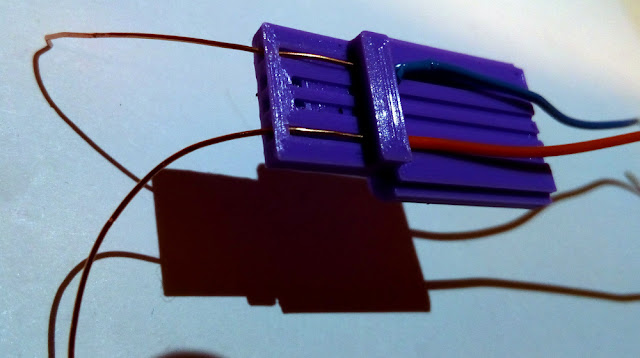
The first part is the bottom in which you need to insert the wires. The second part is the top which you should glue and press on to the bottom part when the wires are placed. The top part has ridges that help keep the wires in place.


This is how the files look in my slicer. I use Cura.


Set the quality at 0.2mm and supports on. As these are small parts you could set adhesion also on.

Assembling

I used solid copper wire with a diameter of 0.5mm. That worked very well.

I took a slightly different approach to assembling as what the original developer described.

First I stripped the wires.


Then I pulled the stripped part through the holes.

Then I glued the lid on.
The last step was to cut off the excess wire.

The blue wire at the top is GND.
The red wire at the bottom is VCC (5V).
Please test before you actually put it to use to make sure the wires are not twisted. If you mix the wires up you might/will blow up your circuit so test, test, test !!!


The wires are thick enough to fit direct into a breadboard.

You can make the wires any length you want. Short to connect to a powerbank and fit on your desk. Or make them long to connect to a wall outlet with an USB power plug.

I have printed several of these. They are ready to use in my drawer. A really great design.

Til next time
Have fun

Luc Volders

Friday, September 13, 2024

Testing an obstacle avoidance sensor

For an index to all my stories click this text

I was playing around with an obstacle avoiding sensor and want to share my experiences with you.

What is it.

An obstacle avoidance sensor is mostly used in robotics.

The sensor has an infrared led. This led sends out lightin the infrared spectrum which we can not see. the light normally shines streight on.

Next to the infrared led there is a photodiode. That photodiode detects infrared licht.

When the sensor approaches an obstacle the infrared light is reflected back and detected by the photodiode.

Like said, this is mostly used in robotics. The sensor is mounted on a robot and when the robot comes close to a wall or any other obstacle the photodiode sends a signal to the robots controller to alter direction.

The sensor

This is how the sensor looks in real life. Let's have a look at the different parts of it.

On the left you can see the photodiode at the top and the IR led beneath it. They are next to eachother so the there is a maximum chance of detecting any reflection.

In the middle there is a screw with witch you can adjust sensitivity. That means by turning the screw you can adjust the maximum distance at what the reflection is detected.

Next to the header pins there are two leds. The top led is the power led and that is always on whenever the sensor has power. The led at the bottom is off and goes on when an obstacle is detected.

A test setup

To test the sensor I build a simple setup on a breadboard. I connected the sensor to a Raspberry Pi Pico. Here is what the breadboard looks.


The led (I used a blue one) is connected with a current limiting resistor to GND and to GPIO15.

Pico's GND (pin38) is connected to the sensor's GND. and Pico's 5V (pin 40) is connected to VCC. The sensors output (OUT) is connected to GPIO16.

Test program in MicroPython

To test the sensor I wrote a simple program in MicroPython.

import time
from machine import Pin

obstac = Pin(16, Pin.IN)
led = Pin(15, Pin.OUT)

while True:
      print(obstac.value())
      led.value(not obstac.value())
      #led.value(0)
      time.sleep(.2)

In the loop the program constant tests the out pin of the sensor. When that pin's output changes from 1 to 0 (obstacle detected) the led on GPIO15 goes on.

Copy this program, paste it in Thonny and save it as main.py on your Pico. It will work on the Pico, Pico W and Pico2.
Saving it as main.py makes the program run immediately when the Pico is powered up so you can do some tests with a powerbank, phone charger or batteries.

If you want to learn about MicroPython on the Raspberry Pi Pico or Pico W please consider buying one of my books that are listed at the bottom of this page.

First test.

This should immediately work. Just hold your hand above the sensor and move it towards the sensor. At a certain moment the led will go on both on the sensor as well as the blue led.

Now you can adjust the screw in such a way that the leds will go on at your desired distance.

Distance

According to some specifications I found you can adjust the screw so the distance at which the led will go on can be set from 2 to 20 cm.

Just be aware that there are environmental issues that might influence the detection distance. Here are some things you might like to take into consideration.
- Temperature may affect the distance
- TL light might affect the distance
- Sun light might affect the distance
- Direct light shining on the photodiode might affect the distance

The only thing I want to say is that you should adjust the sensivity screw in your real-life setup.

Some tests

Here are the results of some tests I performed.


All leds are OFF because there is no obstacle in front of the sensor.


A shining transparant box was put in front of the sensor and at a distance of 8 cm the obstacle was detected.


A black piece of paper was put in front of the sensor and at 6cm it was still not detected.


The black paper was detected at 2.5 cm.
This means that the black paper absorbed (did not reflect) a lot of infrared light so it was not detected until it was at a short distance.


A white piece of printer paper was detected at 8 cm distance. The white color reflects the infrared light more so the paper was earlier detected.


A black shining object was detected at 4cm. This means that the black color absorbed some infrared light but the shing surface reflected also some infrared light.


A book (yes my book about the Pico) with a shining green cover reflected the infrared light at a larger distance so it was already detected at about 8.5cm

Water ???

Solid obstacles: OK
But how about fluids.

If you want to reproduce this test yourself just make sure the electronics don't get wet. Water and electronics don't mix and you might damage your sensor or pico beyond repair.


I filled a white bowl with a small layer of water and help the breadboard above it.
The led stayed off: no obstacle detected.


I used a bottle of water to gradually fill the bowl and yes !!!
At a certain moment the led went on. So water reflects the infrared light.


Concluding

First let me state that obstacles are detected very well.
In the demo program you can lower the delay and that will not affect the working of the sensor. So in real life you should use an interrupt for testing for an obstacle which is the fasted method.

The obstacle avoidance sensor detects obstacles but does not give any indication at what distance the obstacle is 'seen'. The difficulty lies in different materials reflecting the infrared light more or less.
If you need to measure distance then use an HC-SR04 ultrasonic sensor.

This means that you should adjsut the sensivity screw so that the obstacle is detected at a larger distance when you are working with a fast moving object like a remote controlled car. That is because you will need time to shut the motor down. But you also need to take the obstacles material in count as black obstacles are seen later.

I was specially impressed when I realised that the sensor also detected water as an obstacle.
I did not try but wonder if a black bowl would make a difference.

And remeber: you can always use this sensor inverted. Meaning that an alarm is given when an obstacle is removed like the lid of a box is taken off.

Till next time
Have fun

Luc Volders


Friday, January 20, 2023

Importing libraries in Wokwi

For an index to all my stories click this text.

Few months ago I was playing with Wokwi. And then I discovered something that even the developers did not know was possible. And things like that always flatters my ego.

For those that are not familiar with Wokwi here is a short description.

Wokwi is a simulator. It simulates Arduino, Raspberry Pi, ESP32 and Raspberry Pi Pico controllers. You can build simulations using the C++ and MicroPython languages. I did a more in depth story on Wokwi earlier on this weblog. You can find that story here: http://lucstechblog.blogspot.com/2022/04/simulate-your-controllers-with-wokwi.html  Wokwi self can be found here: https://wokwi.com/

What I wanted to do is to attach a TM1637 display to a Raspberry Pi Pico and simulate that in Wokwi. The TM1637 display is available in Wokwi but there is no support for MicroPython. Only the Arduino IDE is supported. Bummer !!

Then I had an idea.

I opened a new project in Wokwi. I chose for opening a project with MicroPython on Pi Pico.


With the + sign I added the TM1637 display and attached the wires.

As I wrote in my books Raspberry Pi Pico Simplified and Raspberry Pico W Simplified most MicroPython libraries are just programs.


I downloaded the library and in Wokwi I opened a new file and called it tm1637.py and pasted the code from the Library. In the main.py program I put import tm1637 and that's it.


And there you go. Worked like a charm.

Just make sure that you give the new opened file in Wokwi exact the same name as the library has. If you differ the program will not be able to find the library, and generally the library will not work.

You can find the example here:
https://wokwi.com/projects/339373435833549395

There is a program called main.py and that imports tm1637.py which is the library and a separate file. The library is copied from the github page and just pasted into the file.

If you need to work with the TM1637 in Wokwi just copy my project in Wokwi and add your own MicroPython code.

I can not guarantee that this trick will work with any library you find on the internet. Just try it. You can not break anything physically in a simulation................

On the Wokwi channel in Discord I mentioned this to Wokwi's developers. They did not know that this was possible and they said that they would put this into the documentation. And that indeed flatters my ego.

Have fun and be creative !
Till next time.

Luc Volders


Friday, May 6, 2022

Interrupts: WTF happened

For an index to all my stories click this text.

Some of you pointed out that there was a problem with my code in the "More buttons on fewer pins" story. Now I must admid that I wrote that story some time ago, published it and forgot about it.
When some readers however mailed me that there was a problem with the software I had to dive into this again. And indeed WTF happened.

Well what happened was that a new version of the Arduino software had some alterations in the interrupt routine. That made the ESP series (ESP8266 and ESP32) microcontrollers run berserk.

What's behind it.

Sometimes programs are loaded from flash memory when run. That works fine for a lot of programs but poses a problem when fast processing is involved.
The Arduino IDE therefore changed the way it handles interrupts. It wants the interrupt handling routine to run in RAM so it is always available when needed, and needs not to get loaded first during execution of a program.

Next to that it is recommended that no delay() command is used in the interrupt routine. As a matter of fact that makes sense. Interrupts generally need to be handled as fast as possible because it may happen that when the interrupt routine is being handled at the same time a new interrupt is initiated.

However in my program that handles a button press speed is not the issue. The interrupt routine is processed a lot faster then you would press another button. But my endeavours in my little corner of the universe is of course of no concern to the developers of the Arduino IDE.

It made however an impact on some of my programs and of course the chapter on interrupts in my book ESP32 Simplified. You can find details on my book here: http://lucstechblog.blogspot.com/2020/06/esp32-simplified-my-book-in-english-now.html

The solution

Luckily the alterations to get things working again are small.

attachInterrupt(digitalPinToInterrupt(D5), buttonpress, FALLING);


In the setup() routine the interrupts are initiated with this line. And that stays the same. The interrupt is attached to pin D5 and when that button is pressed it calls the "buttonpress" routine.

void buttonpress()
{
  // button 1 ==> 011
  if (digitalRead(D5)== LOW && digitalRead(D6)== HIGH && digitalRead(D7)== HIGH)
  {
    strip.setPixelColor(0, 0,255,0);
    strip.setPixelColor(1, 0,0,0);
    strip.setPixelColor(2, 0,0,0);
    strip.setPixelColor(3, 0,0,0);
    strip.setPixelColor(4, 0,0,0);
    strip.setPixelColor(5, 0,0,0);
    strip.setPixelColor(6, 0,0,0);
    strip.show();
    delay(500);
  }


This is part of the "buttonpress" interrupt routine. This is where we need to make the changes. First we need to alter void buttonpress() in ICACHE_RAM_ATTR void buttonpress() So a command is put in front of void buttonpress(). That command is ICACHE_RAM_ATTR and that makes sure that this part of the program is loaded into RAM before the program starts.

Next the delay(500) line must be left out.

So the new first part of the program is:

ICACHE_RAM_ATTR void buttonpress()
{
  // button 1 ==> 011
  if (digitalRead(D5)== LOW && digitalRead(D6)== HIGH && digitalRead(D7)== HIGH)
  {
    strip.setPixelColor(0, 0,255,0);
    strip.setPixelColor(1, 0,0,0);
    strip.setPixelColor(2, 0,0,0);
    strip.setPixelColor(3, 0,0,0);
    strip.setPixelColor(4, 0,0,0);
    strip.setPixelColor(5, 0,0,0);
    strip.setPixelColor(6, 0,0,0);
    strip.show();
  }


Famous last words.

So to get your programs that use an interrupt routine working again put ICACHE_RAM_ATTR in front of the line that defines the start of the routine and remove all delay() statements from your interrupt routines.

PHEW !!!
Easier as I thought.

Till next time.

Luc Volders

Friday, April 8, 2022

Visible indication for the: more buttons on fewer pins

For an index to all my stories click this text.

In a previous story I showed how to attach many buttons on just a few IO pins. I did this by using diodes to binary decode the buttons. Sounds complicated but it really isn't and it is a great way to have more buttons, switches, door contacts, pir sensors etc without sacrificing too many IO pins. You can re-read that story here: http://lucstechblog.blogspot.com/2019/07/more-buttons-on-fewer-pins.html
 
The setup was just an example for the tutorial. And in real life pushing one of the buttons would evoke some action. However, how about immediate feedback. Then I had this idea.

Let us look at some basic electronics.


On the left you see the symbol for a diode and on the right side the symbol for a led. That shows that a led is basically a diode that transmits light. Duh..... Hence the name Led: Light Emitting Diode.

So what if I would exchange some of the diodes in my project by a leds. That would show which button was pressed, no matter what actions would follow you would get an instant feedback,


Here you can see that the strip at the right side of the diode points to where the - side is. This is the side to which the buttons are connected. When replacing a diode by a led test with a battery which side of the led is the + and which is the - side. Then replace the diode by a led using the same polarity.

At the buttons where just 1 diode is attached replace that diode by a led. At the buttons where multiple diodes are attached hust replace 1 of the diodes by a led.

That's all.

What leds to use.

Not all led's can be used as for some the forward voltage is to high. The dimmed red and green ones worked for me as did the clear red ones. Just experiment and see what works best in your setup.


Here you can see my setup with 7 buttons attached to just 3 IO pins of a Wemos D1. In this setup I replaced 3 diodes (as a test) with clear red leds.


And here you can see what happened when I pushed the first button. From the string of Neopixels only the first one lightened up just as it should but the led attached to the button also lightened up.

There you go. An immediate feedback when you press a button.

Till next time
have fun

Luc Volders


Friday, March 18, 2022

More buttons on fewer pins

For an index to all my stories click this text

I am working at at larger project in which I need an ESP8266 to send certain data over wifi depending on buttons being pressed. Nothing exiting you might think. However in one particular case I might need a lot of buttons.

The ESP8266 boards like a NodeMCU module or a Wemos D1 have about 11 digital I/O ports available. So I could attach a button to each I/O pin giving me 11 buttons. However that leaves no room for attaching other items like control-leds or a display.

It gets worse when you are working with really tiny controllers like the Attiny85. This micro-controller has, when normally used, just 5 I/O pins.

Let's have a look how the commercially available keyboards work.


As you can see they are build in a matrix layout. The 4 x 4 matrix has 4 rows and 4 columns. In the software you make sure that one of the rows is set to LOW, the rest to HIGH. This way you can test which column gets the LOW signal and that intersection is the key being pressed. If none of the columns gets a LOW signal the next row is set to LOW and the test starts over.

This works great however has some flaws for me. First the software makes the controller load high. You actively have to set each row in its turn LOW and the rest HIGH and then test which column gets the LOW signal. This will keep your controller pretty busy.

Next to that for 12 buttons you will need 7 I/O pins. For 16 buttons you will need 8 pins. This leaves little room for control leds although I could use neopixels for that which only take one I/O port. And this is no option for working with an Attiny85 with its mere 5 I/O pins.

I needed something better. So started thinking.

The binary system.

Let's look at the binary system. If I have one wire it can be HIGH or LOW. When using two wires there are already more possibilities:

LOW   LOW
LOW   HIGH
HIGH  LOW
HIGH  HIGH


So how do I put that to use. Lets attach switches to the 2 wires using this principle.


Look at the schematic. The two pull up resistors make sure that if no key is pressed both lines are HIGH. That is the HIGH-HIGH state.
There are three buttons.
The first button is connected to the first line, second button to the second and third button to both.
The idea is ok but it just does not work. If you press button one the ground will indeed be connected to the first line, but it will flow through the wire connected to button three. And as this button is connected to both wires, so ground will be connected to both wires.
We have to prevent that ground will be connected to two wires at the same time and that is easy.


Just put diodes on the wires connected to the buttons.
If you press button 1 ground will be connected to line 1. Ground wants to flow to button three but is prevented by the diode so can not flow back to line 2.

That is it. So with two lines we can use three switches.


Above you can see the breadboard setup. And best part: it really works.

The binary system with 3 wires

Using 3 wires we have the following posibillities:

LOW   LOW   LOW
LOW   LOW   HIGH
LOW   HIGH  LOW
LOW   HIGH  HIGH
HIGH  LOW   LOW
HIGH  LOW   HIGH
HIGH  HIGH  LOW
HIGH  HIGH  HIGH


Leaving the last one out because that is when no button is pressed, we have 7 posibillities. So 7 buttons with just 3 wires.

Lets look at the schematics again.


Not a lot different from our fist setup with only two wires.
Does it look familiar somewhere ???
Well if you are a faithfull reader of this blog you might recognise this from my stories on Charlieplexing. The hardware setup is not quite the same but it has some resemblance. You can re-read that story here:
https://lucstechblog.blogspot.com/2017/09/charlieplexing.html or search my index page for all the Charlieplexing stories: http://lucstechblog.blogspot.com/p/index-of-my-stories.html

Adding visual feedback

I wanted a visual feedback for testing purposes. For that I added a string of 7 neopixels. The reason is obvious: attaching a bunch of neopixels can be done with just 1 I/O pin. For those not familiar with the term: neopixels are adressable RGB leds officially called WS2812. For basic information on Neopixels re-read this story: http://lucstechblog.blogspot.com/2015/10/neopixels-ws2812-intro.html

The software.

Let's start with the software in Arduino IDE (C++).


#include <Adafruit_NeoPixel.h>
#define PIXEL_PIN    D8    
#define PIXEL_COUNT 7

Adafruit_NeoPixel strip = Adafruit_NeoPixel(PIXEL_COUNT, PIXEL_PIN, NEO_GRB + NEO_KHZ800);

void setup() 
{
  pinMode(D5, INPUT);
  pinMode(D6, INPUT);
  pinMode(D7, INPUT);
  attachInterrupt(digitalPinToInterrupt(D5), buttonpress, FALLING);
  attachInterrupt(digitalPinToInterrupt(D6), buttonpress, FALLING);
  attachInterrupt(digitalPinToInterrupt(D7), buttonpress, FALLING);
  strip.begin();
  strip.show();

}

void loop() 
{

}

void buttonpress()
{
  // button 1 ==> 011
  if (digitalRead(D5)== LOW && digitalRead(D6)== HIGH && digitalRead(D7)== HIGH)
  {
    strip.setPixelColor(0, 0,255,0); 
    strip.setPixelColor(1, 0,0,0);
    strip.setPixelColor(2, 0,0,0);
    strip.setPixelColor(3, 0,0,0);
    strip.setPixelColor(4, 0,0,0);
    strip.setPixelColor(5, 0,0,0);
    strip.setPixelColor(6, 0,0,0);
    strip.show(); 
    delay(500);
  }
  // button 2 ==> 101
  if (digitalRead(D5)== HIGH && digitalRead(D6)== LOW && digitalRead(D7)== HIGH)
  {
    strip.setPixelColor(0, 0,255,0); 
    strip.setPixelColor(1, 0,255,0);
    strip.setPixelColor(2, 0,0,0);
    strip.setPixelColor(3, 0,0,0);
    strip.setPixelColor(4, 0,0,0);
    strip.setPixelColor(5, 0,0,0);
    strip.setPixelColor(6, 0,0,0);
    strip.show(); 
    delay(500);
  }
  // button 3 ==> 110
  if (digitalRead(D5)== HIGH && digitalRead(D6)== HIGH && digitalRead(D7)== LOW)
  {
    strip.setPixelColor(0, 0,255,0); 
    strip.setPixelColor(1, 0,255,0);
    strip.setPixelColor(2, 0,255,0);
    strip.setPixelColor(3, 0,0,0);
    strip.setPixelColor(4, 0,0,0);
    strip.setPixelColor(5, 0,0,0);
    strip.setPixelColor(6, 0,0,0); 
    strip.show(); 
    delay(500);
  }
    // button 4 ==> 100
    if (digitalRead(D5)== HIGH && digitalRead(D6)== LOW && digitalRead(D7)== LOW) //
  {
    strip.setPixelColor(0, 0,255,0); 
    strip.setPixelColor(1, 0,255,0);
    strip.setPixelColor(2, 0,255,0);
    strip.setPixelColor(3, 0,255,0);
    strip.setPixelColor(4, 0,0,0);
    strip.setPixelColor(5, 0,0,0);
    strip.setPixelColor(6, 0,0,0);
    strip.show(); 
    delay(500);
  }
    // button 5 ==> 001
    if (digitalRead(D5)== LOW && digitalRead(D6)== LOW && digitalRead(D7)== HIGH) //
  {
    strip.setPixelColor(0, 0,255,0); 
    strip.setPixelColor(1, 0,255,0);
    strip.setPixelColor(2, 0,255,0);
    strip.setPixelColor(3, 0,255,0);
    strip.setPixelColor(4, 0,255,0);
    strip.setPixelColor(5, 0,0,0);
    strip.setPixelColor(6, 0,0,0);
    strip.show(); 
    delay(500);
  }
    // button 6 ==> 010
    if (digitalRead(D5)== LOW && digitalRead(D6)== HIGH && digitalRead(D7)== LOW) //
  {
    strip.setPixelColor(0, 0,255,0); 
    strip.setPixelColor(1, 0,255,0);
    strip.setPixelColor(2, 0,255,0);
    strip.setPixelColor(3, 0,255,0);
    strip.setPixelColor(4, 0,255,0);
    strip.setPixelColor(5, 0,255,0);
    strip.setPixelColor(6, 0,0,0);
    strip.show(); 
    delay(500);
  }
    // button 7 ==> 000
    if (digitalRead(D5)== LOW && digitalRead(D6)== LOW && digitalRead(D7)== LOW) //
  {
    strip.setPixelColor(0, 0,255,0); 
    strip.setPixelColor(1, 0,255,0);
    strip.setPixelColor(2, 0,255,0);
    strip.setPixelColor(3, 0,255,0);
    strip.setPixelColor(4, 0,255,0);
    strip.setPixelColor(5, 0,255,0);
    strip.setPixelColor(6, 0,255,0); 
    strip.show(); 
    delay(500);
  }
}


Before I get a load of comments in my mail on this code let me make it clear that this source code can be optimised a lot. That would make it a lot more complicated for beginning programmers to comprehend. So adjust it for your own purposes.

The program starts with initialising the Neopixel library and attaching the library to pin D8.

In the setup routine the input lines D5, D6 and D7 are defined, and we attach an interrupt to each of these lines. All the interrupts point to the same routine: buttonpress on a FALLING signal. This means that when a button is pressed (connected to ground) the program starts the interrupt routine.

This is a big advantage over the software for the commercial keyboards. Your software is not constant sending LOW signals to row-pins and polling the collumn-pins. We just wait till a key is pressed and in the mean time the micro-controller has loads of time for other tasks.

When a button is pressed the program jumps to the buttonpress() routine.

Here is a closer examination about what happens when button 4 is pressed:

    // button 4 ==> 100
    if (digitalRead(D5)== HIGH && digitalRead(D6)== LOW && digitalRead(D7)== LOW) //
  {
    strip.setPixelColor(0, 0,255,0);
    strip.setPixelColor(1, 0,255,0);
    strip.setPixelColor(2, 0,255,0);
    strip.setPixelColor(3, 0,255,0);
    strip.setPixelColor(4, 0,0,0);
    strip.setPixelColor(5, 0,0,0);
    strip.setPixelColor(6, 0,0,0);
    strip.show();
    delay(500);
  }

The diodes from button 4 are attached to D6 and D7. So when button 4 is pressed D5 will get no signal and the pull-up resistor makes sure the line is HIGH. Line D6 and D7 will be connected to ground. This is what the if statement analyses.

Next part is just setting 4 of the neopixels to green, so we know for sure button 4 is pressed. The delay makes sure that the neopixels are lit before we go on.

Simple and efficient !!!
We got lots of room and time for the processor to perform other tasks in stead of constant sending signals and polling lines and have the risk of missing a keypress.

You will notice that the only thing you have to do is to alter D5, D6, D7 and D8 and this will also work on the ESP32 or any of the Arduino family even on the humble Attiny85 !!!

Basic program

No I am not forgetting ESP-Basic, - my used to be - favorite rapid devellopment environment (that's a mouth full). In fact the hardware setup is so efficient that writing the software in Basic is very easy. It looks a lot like the C++ program.


interrupt d5, [CHANGE]
interrupt d6, [CHANGE]
interrupt d7, [CHANGE]

neo.setup(d8)
neo.cls()

wait

[CHANGE] 

interrupt d5
interrupt d7
interrupt d6

if ((io(pi,d5) = 0) and (io(pi,d6) = 1) and (io(pi,d7) = 1)) then
neo.cls()
neo(0,250,250,250)
endif
 
if ((io(pi,d5) = 1) and (io(pi,d6) = 0) and (io(pi,d7) = 1)) then
neo.cls()
neo(0,250,250,250)
neo(1,250,250,250)
endif

if ((io(pi,d5) = 1) and (io(pi,d6) = 1) and (io(pi,d7) = 0)) then
neo.cls()
neo(0,250,250,250)
neo(1,250,250,250)
neo(2,250,250,250)
endif

if ((io(pi,d5) = 1) and (io(pi,d6) = 0) and (io(pi,d7) = 0)) then
neo.cls()
neo(0,0,0,250)
neo(1,0,0,250)
neo(2,0,0,250)
neo(3,0,0,250)
endif

if ((io(pi,d5) = 0) and (io(pi,d6) = 0) and (io(pi,d7) = 1)) then
neo.cls()
neo(0,250,0,0)
neo(1,250,0,0)
neo(2,250,0,0)
neo(3,250,0,0)
neo(4,250,0,0)
endif


if ((io(pi,d5) = 0) and (io(pi,d6) = 1) and (io(pi,d7) = 0)) then
neo.cls()
neo(0,0,250,0)
neo(1,0,250,0)
neo(2,0,250,0)
neo(3,0,250,0)
neo(4,0,250,0)
neo(5,0,250,0)
endif


if ((io(pi,d5) = 0) and (io(pi,d6) = 0) and (io(pi,d7) = 0)) then
neo.cls()
neo(0,250,0,250)
neo(1,250,0,250)
neo(2,250,0,250)
neo(3,250,0,250)
neo(4,250,0,250)
neo(5,250,0,250)
neo(6,250,0,250)
endif

delay (500)

interrupt d6, [CHANGE]
interrupt d7, [CHANGE]
interrupt d5, [CHANGE]

delay (500)
cls
wait 

end


A quick examination of the program:

interrupt d5, [CHANGE]
interrupt d6, [CHANGE]
interrupt d7, [CHANGE]

neo.setup(d8)
neo.cls()

wait

This is the main part where the interrupts are defined and the neopixels are attached to IO pin D8

[CHANGE]

interrupt d5
interrupt d7
interrupt d6

This is a tricky part.

If the [CHANGE] routine is called (as a button is pressed) we do not want that the routine is accidentally (think bouncing buttons) called again. So these commands disable the interrupts.

if ((io(pi,d5) = 1) and (io(pi,d6) = 0) and (io(pi,d7) = 0)) then
neo.cls()
neo(0,0,0,250)
neo(1,0,0,250)
neo(2,0,0,250)
neo(3,0,0,250)
endif

This is almost the same as in the C++ routine and is the part where button 4 is processed.
As you can see D5 gets no signal so that will be pulled HIGH by the pull-up resistors. D6 and D7 should both get a LOW signal. If this is true the first 4 neopixels (0 to 3) will be set to blue.

interrupt d6, [CHANGE]
interrupt d7, [CHANGE]
interrupt d5, [CHANGE]

These lines will activate the interrupts anew when the routine has finished.

As there are two delay (500) statements the program will register a button-press once every second. That should be fast enough for most purposes.

Expanding

Using 4 I/O pins you can attach 15 buttons which is enough for a simple calculator keyboard. And with 5 I/O pins you can attach 31 buttons !!
I am sure you can work the schematics out for yourselves.

Let's elaborate on this.
With 5 I/O pins you can attach 31 buttons. Now suppose you use one of these 31 buttons as a Shift key and another one as a Second Function key you could build a simple ASCII keyboard using an Arduino Pro Micro which has a real USB interface.

Pros and cons.

So why isn't this used more often, and why are all the commercial keyboards build as a matrix ssytem and not in this way.
The answer is simple: costs.
Using the matrix layout you only need buttons. In this setup you need buttons and diodes which is more expensive and makes the PCB a bit more complicated.

The pros for me weigh much more as the cons.
For the 12 button commercial version you will need to use 7 I/O pins on your controller. I only need 4 and can use 15 buttons (3 more).
The additional costs are so small that they are neglectable. At the moment of this writing you can buy 100 diodes for 50 cents !!!
Next to that the software does not put a heavy load on my controller and is much easier to program.

And last but not least: on an Attiny85 I can attach 15 buttons and a string of neopixels at the same time !!!

Real world setup


Above you can see my real world setup and test. The only difference with the schematics in this story is that I attached a seperate power supply for the Neopixels.

That's it for now.

Till next time and have fun.

Luc Volders