Friday, August 23, 2024

First look at the Raspberry Pi Pico2

For an index to all my stories click this text.

January 2021 the Raspberry Pi Pico was released. Until that time we had Arduino's and ESP series microcontrollers dominating the market and hobbyist landscape. And the Pico took us by surprise. We were used to the linux machines of the Raspberry company and suddenly they were into microcontrollers.

The Pico microcontrollers made an enormous impact as they were made in Europe and have a very low price for what they are offering (about 5 euro / 5 USD)

A year later they presented the Raspberry Pi Pico-W which has Wifi capabilities and was a serious contestant for the ESP8266 and ESP32.

And just 2 weeks ago the successor was announced the Raspberry Pi Pico2 and it is already available over here in the Netherlands. This is the version without Wifi.

No Wifi means you have to look at it like a (very) cheap Arduino with more IO pins, higher clock-rate and loads more storage and memory.

Differences.

A new chip must bring some differences and especially when there is a 3 year time-gap.

Pico   : RP2040 Dual core Arm Cortex M0+ processor at 133Mhz
Pico2 : RP2350 Dual core Arm Cortex M33 processor at 150Mhz
        or RISC-V Hazard3 processor (choosable by software)

Pico   : 264Kb Ram and 2Mb flash memory
Pico2 : 520Kb Ram and 4Mb flash memory

Pico   : 16 PWM channels
Pico2 : 24 PWM channels

Pico   : 8 × Programmable I/O (PIO) state machines
Pico2 : 3 × Programmable IO (PIO) blocks, 12 state machines

A small explanation is needed about the processor. It is not that you have to chose which Pico2 you have to buy. The Pico 2 has standard a Dual core ARM Cortex M33 processor AND a Dual core RISC-V Hazard3 processor on board. They can not work all at the same time but you can chose if you want to work with the M33 or Risc-V processors when the Pico2 boots.

The most eye-catching differences are of course the increased speed (on which later more) and the doubled ram and storage. The increased RAM and storage opens new opportunities for all kinds of projects.

What remains the same:

- USB 1.1 interface for programming
- Micro usb connector
- Low power sleep modes
- 26 multi function GPIO pins
- 2 SPI ports
- 2 I2C ports
- 2 UART ports
- 3 Analog inputs

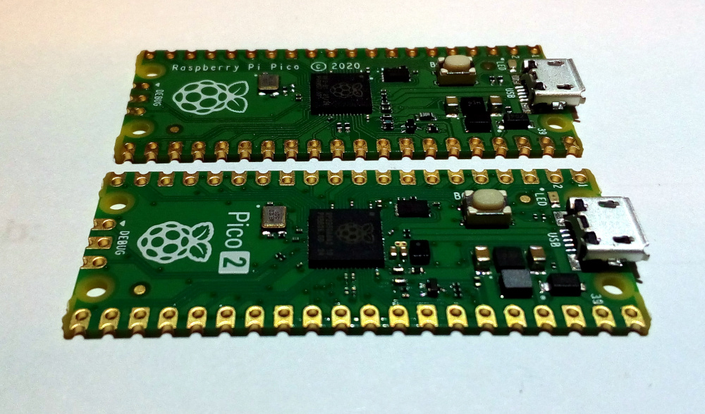
The form factor is the same and the Pico and Pico2 are pin compatible.
This should mean that you can remove a Pico from your project and just drop in a Pico2 for more performance. I have not tested this yet, but I am confident that this will work in most (if not all) cases.


The Pico can be bought with headers and no doubt that will also become the case for the Pico2. But for now you will have to solder the headers yourself if you want to use the Pico on a breadboard.

Programming Languages.

The most popular programming languages for the Pico are MicroPython and C++ (Arduino IDE). For the Pico2 (at the moment of this writing) of those only an early release of MicroPython is available.

If you want to learn more about installing MicroPython, working with libraries and programming please consider buying one of my books listed at the bottom of this page.

For the Pico and Pico2 is the Raspberry C SDK available through the Raspberry Pi foundation.
For both the Pico and Pico2 Adafruit's Circuitpython is available allbeit in an early release version.

The Arduino IDE (C++) for the Pico2 is in development although the developer could not buy the Pico2 for testing at the moment of this writing.

Flash memory

I took a fresh Raspberry Pi Pico and the new Pico2. On the Pico I flashed the latest release of MicroPython and on the Pico2 the beta release which was the only one available at the time of this writing.

Both Pico's have flash memory for storage. The Pico has 2MB and the Pico2 has 4Mb. This is what Thonny's IDE showed what was available.

This is what the Pico has available: 1.4Mb

And this is what the Pico2 offers: 3Mb

The specs say that there should be more memory (2Mb and 4Mb) and that is correct because part of the memory is taken by the MicroPython language.

This means that with the Pico2 we have more free storage as the total memory of the Pico. This offers loads of possibilities for graphics and audio projects. I have some nice audio projects coming up on this weblog and they could really benefit from this increased storage.


Ram

Now let us have a look at RAM memory. This is the memory in which programs run.


The Pico has 228608 bytes which is about 228k memory free when running MicroPython.


The Pico2 has 482432 bytes free. More then twice the memory of the Pico is free. This means we can make large programs or work with huge amounts of data.

Speed test

I tested the speed differences with MicroPython.
For the Pico2 there are 2 versions of microPython available. The first version runs microPython on the Cortex M33 core and the second version runs on the Risc-V core. I tested both and compared them to the same program running on the Pico.

Just for the record. The original Pico can be overclocked. That means that we can change (increase) the clock frequency of the Pico so it runs faster (there will be a story on this weblog over this feature). At this moment you can not push the clock frequency of the Pico2 over the standard 150mhz as Micropython will not allow it.

For testing I used the following program:

import time
start = 10000
end = 11000

starttim = time.ticks_ms()

print ("Searching the Prime Numbers from ", start, "to ", end)
for number in range (start, end + 1):
    if number > 1:
        for i in range (2, number):
            if (number % i) == 0:
                break
        else:
            #print (number)
            continue

endtim = time.ticks_ms()
print(endtim-starttim)

This program is a combination of two of the tips you can find on my MicroPython tips page:


https://micropython-tips.weebly.com/

The program runs through all numbers between 10000 and 11000 and test for prime numbers. If you remove the # in the line #print (number) the program will actually print the found prime numbers. The test was done without the numbers being printed.


The original Pico needed 12707 microseconds to run this program. That is almost 13 seconds.


The Pico2 running the M33 cores needed 6683 microseconds. Just a bit less then 7 seconds. This means that it runs at almost double the speed of the original Pico.


The Pico2 running the hazard33 core (Risc-V) needed 7017 microseconds which is just a bit over 7 seconds.

So the Pico 2 runs about twice as fast as the original Pico in this test.

The speed difference is not just because the increase of the clock (from 133Mhz to 150Mhz) but mostly because the M33 cores do the job far more efficient as the Pico's original M0 core.

Please be aware that the results are from a beta release of MicroPython. The official releases may even bring better results.

The price.

The Raspberry Pi Pico2 is now available in the Netherlands for 5,95 Euro. An unbelievable low price for such an extensove development board. Compare that to the price of an original Arduino and you can clealy see who the winner is.

Concluding.

For about 1 euro more as the original Pico you will get twice the memory and about twice the speed. And that in a package of the same size which is pin compatible.

For a lot of projects that already are around the extra speed and memory are not needed. However the price difference makes the choice easy. And no doubt a lot of new projects will emerge that will use that extra speed and memory and will bring projects we never though would be possible.

Pico2-W ???

Yes there will be a version with Wifi. The Raspberry Organisation confirmed that it will be available by the end of this year.

Till next time
have function

Luc Volders

Friday, August 16, 2024

Let two microcontrollers talk over Uart

For an index to all my stories click this text.

In a previous story I demonstrated how you could connect an ESP32 to a Raspberry Pi Pico and send data from the ESP to the Pico. This was not limited to communication between an ESP32 and A Raspberry Pico but could be used by most microcontrollers. The only thing you have to do is to adapt the pin numbers of the connected IO pins in the MicroPython programs.
You can find that story here : http://lucstechblog.blogspot.com/2024/08/let-microcontrollers-talk-to-eachother.html

As this works fine there are limitations: You can only send a few dedicated signals from one micro controller to the other.

If you want to have a full fledged communication between two micro's you'll need a different approach.

UART

The word UART is an abbrevation of universal asynchronous receiver-transmitter. It is a serial protocol develloped for communication between different devices. And that is just what we are going to do.

UART can not simply transfer text. It transfers binary data. Luckily there is a lot of intelligence build into MicroPython that makes life a lot easier for us.

To send data over an UART connection you can simply use:
uart.write("This is my text")

The second microcontroller receives this as a binary stream. So we have to decode it into something we can understand. That is done as follows:

        serinput = uart0.read(20)
        if serinput != None:
          received_data = serinput.decode("utf-8")

The number 20 in uart0.read(20) defines the length of the UART buffer. If the amount of information received is larger as 20 characters it wil be divided into multiple parts.

For safety in the following simple examples a buffer size of 20 is enough.

The breadboard setup

For this experiment I going to connect UART2 of the ESP32 to UART0 of the Raspberry Pi Pico. Both microcontrollers have multiple UART ports. You may use different ports. just make sure to adjust the pins accordingly.

For testing the communication I connected a pusbutton to the ESP32 and a led to the Raspberry Pi Pico.


The pushbutton is with a 10K pull-up resistor connected to IO pin 34 of the ESP32.
The led is connected with a 220 ohm current delimiting resistor to IO pin 15 of the Raspberry Pi Pico.

The UART2 pins of the ESP32 are IO Pin 2 and 15. IO Pin 2 is TX (transmit) and IO Pin 15 is RX (receive).
The UART0 pins of the Raspberry Pi pico are IO pin ) and 1. Pin 0 is TX (transmit) and pin 1 is RX (receive).

To have the two microcontrollers talk to eachother you need to connect the Transmit Pin from the ESP32 to the Receive Pin of the Raspberry Pi Pico and the otherway round. That is what I did in this breadboard setup.

The ESP32 TX pin (2) is connected to the Raspberry Pi Pico's RX pin (1)
The ESP32 RX pin (15) is connected to the Raspberry Pi Pico's TX pin (0)

The ESP32 MicroPython program

The ESP32 is programmed to send the text "led on" to the Raspberry Pi Pico when the button is pressed. here is the fullo code:

'''
ESP32 program to send data over uart
'''

from machine import UART, Pin
import time

button = Pin(34, Pin.IN)

uart = UART(2, baudrate=9600, tx=2, rx=15)

status = 0

while True:
      if (button.value() == 0) and status == 0:
          uart.write("led on")
          print("The led goes ON")
          status = 1
      if (button.value() == 1) and status == 1:
          uart.write("led off")
          print("The led is OFF")
          status = 0
      time.sleep(.3)

This code mostly speaks for itself but I will pick out a few important lines.

uart = UART(2, baudrate=9600, tx=2, rx=15)

This line creates an instance with the name uart. UART 2 is chosen, the baudrate is set to 9600 baud and the transmit (tx) pin is GPIO 2 and the receive pin is set to GPIO 15. Make sure the baudrate in the ESP32 and the Pico program are set to the same. Higher baudrates are of course allowed.

          uart.write("led on")

This is all it takes to send the text "led on" to the Raspberry Pi pico.

The status variable makes sure the the command "led on" or "led off" is only send once.
First time status is zero. And when you press the button the button.value = 0 and status is 0 so "led on" is send. The next time in the loop (if the button is still pressed) status is 1 and button.value is 0 so nothing happens.
The same procedure is copied for when the button is not pressed.
This makes sure that "led on" or "led off" is only send once. So the Uart communication is limited which gives us lots of time to do other things in between.


The Raspberry Pi Pico MicroPython program

The Raspberry Pi Pico is programmed to receive data from the ESP32. When the text "led on" is received the attached led will be set on. When the text "led off" is received the led is set off again.

'''
program to receive data over uart
from raspberry pico
'''

from machine import UART, Pin
import time

led = Pin(15, Pin.OUT)

uart0 = UART(0, baudrate=9600, tx=Pin(0), rx=Pin(1))

while True:
    if uart0.any():
        print("Serial data available")
        serinput = uart0.read(200)
        if serinput != None:
          print(serinput.decode("utf-8"))
          if serinput.decode("utf-8") == "led on":
            led.on()
          if serinput.decode("utf-8") == "led off":
            led.off()
        time.sleep(.1)

Ok this needs some more explanation.

    if uart0.any():

This line tests if there is any data received on the UART pins. If not the whole routine is skipped. This gives us time to do other things in between when needed.

        serinput = uart0.read(200)

A serial buffer is created of 200 characters.
If more characters are received only the first 200 characters are remembered. You can expand the buffer or make it smaller adjusting to your needs.
For this small example a buffer of 20 caharcters would laready be too much.

        if serinput != None:

We skip the rest of the routine if None is received. That means the buffer is empty.

          print(serinput.decode("utf-8"))
          if serinput.decode("utf-8") == "led on":


The text in the buffer is printed in Thonny's shell for our convenience.
The received information that is contained in the buffer and stored in the serinput variable is in binary form. So it is decoded to human readable information by the serinput.decode("utf-8") command.

That's all there is to it.

Testing.

Just press the button and after a short delay the led wil go on. Keep the button pressed and the led wil stay on. Release the button and the led will go off.

You can see the status of the led printed in Thonny's shell.


Best is to open multiple instances of Thonny so you can look at the shell from the ESP32 and the shell of the Raspberry Pi Pico at the same time.


Experiment succeeded.

This gives lots of opportunities to expand and experiment.
It is easy to expand this to have two way communication so that the Pico can send data back to the ESP.
Both Micro's now can have a lot of sensors and actuators that can be controlled from the other micro.

Till next time
have fun


Luc Volders


Friday, August 9, 2024

Let microcontrollers talk to eachother

For an index to all my stories click this text

I had an idea for a project that needed a lot of IO pins. That sounds easy as there are several stories on this weblog that demonstrate how to get more output or input pins for your microcontroller.

But this was different. I needed a lot of input pins on a microcontroller and depending on the state of those, certain outputs should be set, and a display should show values. And my microcontroller had not e4nough pins to achieve all this.

So I wondered if it was possible to send the output of the IO pins from one microcontroller to the input IO pins of another microcontroller. And for certain reasons I did not want to use serial communication over UART.

ESP32 to Raspberry Pi Pico

I started with trying to connect an ESP32's IO pin to a Raspberry Pi Pico. As a proof of concept I connected 1 IO pin of the ESP32 as an output to 1 IO pin of the Raspberry Pi Pico that acted as the input. Both operate at 3.3V so this should work.

The programs for both the ESP32 and Raspberry Pi Pico are written in MicroPython.
To get this working you should make sure that your IDE (I am using Thonny) is able to open multiple instances.

This is the breadboardsetup.

The GND of the ESP32 is connected to the GND of the Raspberry Pi Pico. If you do not do this the two will not be able to communicate.
Pin 23 from the ESP32 is connected to Pin 16 of the Raspberry Pi Pico. These are the two pins that are used to make the Microcontrollers communicate with eachother.
The Raspberry Pi pico has a led connected to pin 15. This led is connected with a 200 Ohm current delimiting resistor.

That's all for this first test.


The ESP32 program

Here is the full program.

'''
ESP32
send output to other micro on pin 23)
'''

import time
from machine import Pin

outbut = Pin(23, Pin.OUT)

outbut.value(0)

while True:
      outbut(not outbut())
      print(outbut.value())
      time.sleep(1)


I guess the code speaks for itself. Pin23 is defined as the output pin, and it's value is toggled by outbut(not outbut())

The Raspberry Pi Pico program

'''
Raspberry Pi Pico
get input on pin 16)
'''

import time
from machine import Pin

inpbut = Pin(16, Pin.IN, Pin.PULL_UP )
led = Pin(15, Pin.OUT)

while True:
      print(inpbut.value())
      if (inpbut.value() == 0):
          led.off()
      if (inpbut.value() == 1):
          led.on()
          pass
      time.sleep(1)


As this is just a simple test I did not use an external pullup resistor but defined the input pin (Pin 16) as an input with PULL_UP

The input pin gets its data from the ESP32. If the ESP32 sends a 1 (high) then the Pico's led is set on. If the ESP32 sends a 0 (low) then the Pico's led is set off.

The result

And here is what you will see in Thonny's shell.


On the left is Thonny's instance running the Raspberry Pi Pico. On the right you can see the ESP32 sending out a 1 or 0 every second.

At the breadboard you will see that the led blinks evey second when the Raspberry Pi Pico receives a high (1) signal.

A more advanced experiment.

As a test I attached a pushbutton to the ESP32. The goal was to set the led attached to the Raspberry Pi Pico on when the button attached to the ESP32 is pushed.

The breadboard setup is almost identical to the previous version I only attached a pusbutton with a pull-up resistor to the ESP32.


The only thing different from the previous setup is the attached pusbutton which is connected to pin 34 of the ESP32 with a 10K pull-up resistor.


The new ESP32 micropython program

The programn for the Raspberry Pi Pico remains the same. The only difference is in the program for the ESP32.

'''
ESP32
send output to other micro on pin 23
depending on button state
'''

import time
from machine import Pin

button = Pin(34, Pin.IN)
outbut = Pin(23, Pin.OUT)
led = Pin(2, Pin.OUT)

outbut.value(0)

while True:
      if (button.value() == 0):
          outbut.on()
          print(outbut.value())
      if (button.value() == 1):
          outbut.off()
          print(outbut.value())
      time.sleep(.2)


The program send constantly a 0 (LOW) signal on pin 23 and wait tills the button is pressed. When the button is pressed the signal on pin 23 turns into a 1 and that makes the Pico's led go on.

In real life

This works as I thought it would. In real life you possibly want to send more signals from one microcontroller to another.

Please make sure that both microcontrollers work at the same voltage. An ESP32 and a Raspberry Pi Pico both work at 3.3V.  An Arduino however works at 5V, so connecting that to an ESP32 or Raspberry Pico would fry one of these.

A solution to send more info over few pins would be to use binary coding. I covered that in a previous story :
http://lucstechblog.blogspot.com/2019/07/more-buttons-on-fewer-pins.html

That's all for now.
Have fun


Luc Volders


Friday, August 2, 2024

ESP32 Bluetooth Classic part 2

For an index to all my stories click this text.

This is the second story on how to use Bluetooth Classic with the ESP32. The first story covered how to send data from an Android App to the ESP32. You can re-read that story here:
http://lucstechblog.blogspot.com/2024/07/esp32-bluetooth-classic-part-1.html

This story expands the previous one and shows how to display sensor data on your phone's screen. In the first story I build an Android App with MIT's App Inventor. And I am going to modify that app for receiving data from the ESP32.

The hardware

As this is a tutorial and a base for using Bluetooth with the ESP32 I am going to attach two sensors to the ESP32 for generating data. The first one is a simple button and the second one is a Dallas DS18B20 digital thermometer chip. You can easily replace these with any other sensor you might have laying around.

For testing purposes I always build my projects on a breadboard and this is how that looks.


In the previous story I attached a led to D5 with a current delimiting resistor and that is still there. Use this for testing if sending a command from Android to the ESP is still working.

The Dallas DS18B20 is attached to a pull-up resistor and to D19 at the ESP32

Then there is a simple push-button which is connected to D21. I did not use a pull-up resistor on the button but will use the internal pull-up resisitor from the ESP32.

The App Inventor App


As we want to display the values of the button and the digital thermometer we need to add a field to our app's screen. I am just adding one field and the data will be displayed on alternate turns in that field.

So I added a new Label to the screen called Label2


On the left side of the screen click on Label and drag that to your screen. In my sample I put the new Label just above my ridiculous copyright label. The picture shows it as the rectangle.

Next step is to click on "Sensors" at the right side of the screen and click on the Clock sensor and drag that into your screen. It will then appear at the bottom as a non-visible component.
The clock is standard set to fire a signal every second. You can change that to your liking by clicking on the clock icon and then change the properties section at the right side of the designer (not seen in the above picture).

Now move over to the blocks section.


The complete blocks are almost identical to those of the previous story. The only modification is a new block used for receiving data.


This block is executed every second (remember, the property from the clock). First the bluetooth connection is tested and then the text in Label2 is set to the received information.

That is all.
Please delve deeper into App Inventor if you want to make alterations or add more functionality to this simple app. A bit of studying on App Inventor will show that it is fun to play with and easy to develop app's with.

Build the App. Download it to your computer and then transfer it over USB to your phone and install it.

The ESP32 Program

Basically this is the same program as the one from the previous story with some alterations. Let's have a look at the whole program.

#include <OneWire.h>
#include <DallasTemperature.h>

#include "BluetoothSerial.h"

#if !defined(CONFIG_BT_ENABLED) || !defined(CONFIG_BLUEDROID_ENABLED)
#error Bluetooth is not enabled! Please run `make menuconfig` to and enable it
#endif

BluetoothSerial SerialBT;

#define ONE_WIRE_BUS 19

OneWire oneWire(ONE_WIRE_BUS);
DallasTemperature dallas(&oneWire);

String Charrcvd;
String text;
int led=5;
int button=21;

void setup() 
{
  Serial.begin(115200);
  SerialBT.begin("ESP32BTtest"); //Bluetooth device name
  Serial.println("Bluetooth started, now pair your phone");

  pinMode(led, OUTPUT);
  pinMode(button, INPUT_PULLUP);
}

void loop() 
{
   /* 
    * -----------------------------------
    * Bluetooth send part 
    * -----------------------------------
    */
   if(digitalRead(button) == 1)
   {    
   dallas.requestTemperatures();
   SerialBT.print("Temp: ");
   SerialBT.println(dallas.getTempCByIndex(0));
   Serial.println(dallas.getTempCByIndex(0));
   delay(1000);
   }
   else
   {
    SerialBT.println("Button pressed");
    delay(1000);
    SerialBT.println(" ");
   }

  /* 
   *  ----------------------------------
   *  Bluetooth receive part
   *  ----------------------------------
   */
  if (SerialBT.available()) 
  {
    Charrcvd = SerialBT.readString();
       {
        text = text + Charrcvd;
       }
  }
    if (text != "")
      {
      Serial.println(text.substring(0,text.length()-1));
      Serial.println(text.length());
      if (text.substring(0,text.length()-1)== "On") 
        {
          Serial.println("Received: On");
          digitalWrite(led, HIGH);
        }
      if (text.substring(0,text.length()-1)== "Off") 
        {
          Serial.println("Received: Off");
          digitalWrite(led, LOW);
        }
      text = "";
      delay(20);
      }
}


I will not discuss the complete program as a large part is already covered in the previous story on Bluetooth Classic. So check that here
http://lucstechblog.blogspot.com/2024/07/esp32-bluetooth-classic-part-1.html

Let me just highlite some details.

#include <OneWire.h>
#include <DallasTemperature.h>

These lines import the libraries that are needed for the Dallas DS18B20 temperature sensor.

#define ONE_WIRE_BUS 19

The DS18B20 is attached to IO pin 19.

OneWire oneWire(ONE_WIRE_BUS);
DallasTemperature dallas(&oneWire);

An instance for the library is made and called "dallas"

In the loop these are the important parts:

   if(digitalRead(button) == 1)
   {    
   dallas.requestTemperatures();
   SerialBT.print("Temp: ");
   SerialBT.println(dallas.getTempCByIndex(0));
   Serial.println(dallas.getTempCByIndex(0));
   delay(1000);
   }


When the button is not pressed it's line is HIGH and then the Dallas DS18B20 sensor is checked and send over Bluetooth. The important command is SerialBT.print() This is the actual command to send data over Bluetooth.

   else
   {
    SerialBT.println("Button pressed");
    delay(1000);
    SerialBT.println(" ");
   }


If the button is pressed the command SerialBT.println() sends the line "Button pressed" over Bluetooth.

So actually sending data over Bluetooth is pretty easy.
SerialBT.print() sends the data over Bluetooth but does not finish the text line. SerialBT.println() sends and ends the text line. This is the same behaviour as sending text to the Serial Monitor with Serial.print() and Serial.println().

The result

And here is how this works out in real life.


Pressing the green "Led on" and red "Led off" buttons should still work and in the mean time the temperature and button is checked by the ESP32 and displayed in the app.


The next steps.


This should be enough to get you going. There are plenty of projects that can benefit from Bluetooth communication. Think about projects in places where there is no wifi available and you still want to check data. A bycicle computer is a perfect example. And I am sure you can come up with some practical camping projects.

Till next time
have fun

Luc Volders