As these are the dark winter months I am going to give you a great tip on my second hobby: bookbinding. And do not worry. Bookbinding is an ancient craft but we are going to mix it with high-tech here.
One of the most difficult things to do as a hobby bookbinder is to make a cover with relief (also called embossed). I made some of them and it was a tedious job whhich I never really got right. The best I ever made in the past was a bas relief like the picture shows you.
I made this by carving out the letters with a knife. Then I glued the artificial leather on the carton and pressed it in using the letters I carved out. It was minituous work and a mistake was easily made. besides that my carving isn't the best so to say the least: the result was lousy.
However time has passed on and techniques have evolved. So I just invented the best way to make a cover with relief. I am going to show you how this is easily done with a 3D printer.
The first step is to find a typeface you want to use for the job. Best way to do that is just to search free fonts with Google. Mind you a picture can be done in the same way.
In a text processor or DTP package place your text in the desired typeface as large as possible in the middle of a page with plenty room around it.

I used Open Office and the font Janda Elegant Handwriting. This font is freely available on the internet. Just search for Janda Elegant Handwriting in Google and numerous sites emerge from which you can download it freely. However there are many more usable free typefaces which you can download. Just search for 'free fonts' in Google.
Now make a screenshot from the text (or picture) in Open Office. In Windows you'll make a screenshot by pressing Control-Printscreen.
Next step is to open Paint and paste the screenshot in. Then cut out the text as tight as possible and save it under an appropriate name as a JPG file.
Now open your browser again and search for a service that converts JPG images to SVG images. An easy to use site that gives you this service is http://image.online-convert.com/convert-to-svg. Feel free to look around on this site as it offers more converters like audio and video converters. All free to use.
When the file has been converted move it to your project folder on your system.
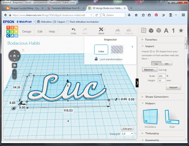
Now go to Tinkercad in your browser and open your account. Create a new design. Next choose import and import your SVG file. Now scale your subject and make sure that you adjust the height to a maximum of 2 milimeters. You can experiment with this but the hight needs to be in pace with the elasticity of the material you are going to use to make your cover with.
That's it. Now download your STL file and the first part is done.
Import the STL file in your favorite 3D printing program, slice it and print it.
Next glue the printed text or picture to the carton that is going to be your board. Let it dry 24 hours before we go to the next step.
When the text glued to the carton is completely dry put glue on the complete plate. make sure you do not forget any corners or curves because we want the leather to stick very well to the carton.
Now put the (artificial) leather on the glued surface.
Next put your pressing foam on.
And last put a pressing plate on top of that. As you can see I am using laminate as a pressing plate. The material is cheap and very strong.
Now put this hambruger in your press and press it really tight. As tight as possible. This means off course that you will not be able to use this technique without a press.
Again let this sit in your press for at least 24 hour.
And behold the fabulous result.
As said you can use this with fonts, frames and drawings. Use it on book covers, boxes, gift cards etc. Use your imagination.
As this is the last posting of this year I whish you all a very Merry Christmass and a Happy, Healthy and Inventive new Year
Until next time.
Have fun.
Luc Volders
I had to learn several programming languages in a relative short time. I learned to program in Python, C++, Mit App inventor, and I learned some HTML. And now I had to learn LUA.
LUA is one of the programming languages used in the ESP8266 boards. It is the standard language for the NodeMCU boards.
So as I had to learn so many languages in a short time I struggled a bit with it.
The Problem:
I wanted to control a bunch of Neopixels (WS2812 leds) with my ESP-8266-01. Luckily enough there is a driver incorporated in the Lua language. The drivers description is as follows:
ws2812.writergb()
Description
Send the RGB Data in 8bits to WS2812
Syntax
ws2812.writergb(pin, string.char(R1,G1,B1(,R2,G2,B2...)) )
Parameters
pin = Supported all the PINs(0,1,2...)
R1 = The first WS2812 though the line's Red Channel's Parameters(0-255)
G1 = The first WS2812 though the line's Green Channel's Parameters(0-255)
B1 = The first WS2812 though the line's Blue Channel's Parameters(0-255)
... You can connect a lot of WS2812...
R2,G2,B2 is the next WS2812's Red, Green and Blue Channel's Parameters
Looks easy enough. So what I did is I send a snippet to the ESP8266-01 looking like this:
ws2812.writergb(3, string.char(120, 25, 80):rep(7))
And all 7 of my Neopixels displayed a nice white/purplisch color.
Note that the first I/O port of the ESP8266-01 being I/O 0 is attached to pin 3......
But that is not what I wanted. I wanted to adress all Neopixels seperately. I wanted each WS2812 to have a different colour.
That made things a bit more complicated.
The syntax for adressing all 7 pixels is:
ws2812.writergb(3,R1,G1,B1,R2,G2,B2,R3,G3,B3,R4,G4,B4,R5,G5,B5,R6,G6,B6,R7,G7,B7)
This looks easy and that is right. However programming it is a bit more complicated.
Solution.
Here is my solution.

I start with defining the colors.
Note that the higher the values, the brighter the Neopixels will be. You can make as many different color combinations as you want.
I made an Array which is as large as the number of Neopixels I had attached. In this case 7 pieces. And then I filled the array with the RGB values: first 3 with blue (b), the next one red (r) and the last 3 with green (g).
And the actual line to set the pixels is:
ws2812.writergb(3,n[1]..n[2]..n[3]..n[4]..n[5]..n[6]..n[7])
So this makes it very easy to adress the individual Neopixels which makes it easy to control them in various projects.
Till next time.
Have fun
Luc Volders
Once you have bought your first ESP8266 modules you will want to start some projects with them.
Now if you have bought the NodeMCU version you are in luck as there is probably the LUA language build in. However if you bought the ESP8266-01 or any other member of this family there is likely to be the AT-command firmware in this module.
The AT-command firmware can be used to communicate with an Arduino. The Arduino does all the I/O and calculations and just sends the results to the ESP which then can send these results over Wifi. Or you can send commands to the ESP which will pass them through to the Arduino that can execute them.
Fun but not very easy to use for novice ESP users like me.
The Lua language is much more easy to understand. It is a high level language which is easy to learn.
And there is more. Not only Lua is available. In the past year a lot of languages have been devellopped for the ESP8266 family. There is Python, Javascript, Lisp and even Basic !!!
At the end of this story I will provide you with links to all the different firmwares that are available for the ESP8266.
Flashing the NodeMCU
To flash the NodeMCU with new firmware you just have to connect the USB cable to your computer, start the NodeMCU Flasher. Get the firmware and instruct the NodeMCU flasher to use that and Push the Flash button.
Flashing the ESP8266-01
This is a bit more tricky. First you will need to build the ESP8266 programming board. You can find it in this post.
Next you will need to load the NodeMCU flasher. You can find the latest version here on the NodeMCU github page: https://github.com/nodemcu/nodemcu-flasher
After you have downloaded and Unzipped it it is ready to flash the latest version of the Lua firmware in your ESP8266.

As you can see the flasher immediately recognizes on wich com-port the ESP8266 is located.

In the config menu you can see that NODEMCU (the LUA firmware) is activated and ready to be flashed.
Now if you press the Flash button nothing will happen. Flashing will not start.
To start flashing you will need to press the Program button (the rightside button on the programmer) and keep it pressed. Then press the Reset button (the leftside button on the programming board).
Now the QR code will be made visible. So will the Mac adresses for the AP (Access point) and STA (Station) be shown. You can write these down or use your Android Phone with a QR code scanner (or your PC with a webcam) for memorising them.
Keep pressing the Program Button (the rightside button) and you will see that the module is slowly being flashed.
When finshed a green circle at the right side of the window will appear with the word Ready next to it. And you're done.
Flashing other firmware.
As stated above there are many firmwares available for the ESP8266: AT-commands, Basic, Java, Lisp, Lua and Python.
To use any of these first click the config tab and choose any free line where it says 'Path of Binary file'. Next to this line is a button. Click that and the fileselector will open. Choose the firmware you want and it will be displayed on that line.
Now choose the right offset in memory. Dont worry normally it is 0x00000 which is already filled in.
Next check which firmware you want to flash and make sure the other lines are unchecked. Now go back to the Operation Tab and proceed as described above and flash your desired firmware.
You're done !!!
To make sure the firmware starts press the reset button on the programming board (the left button).
The links to the available firmwares
First the flash software itself:
https://github.com/nodemcu/nodemcu-flasher
Original AT command set
http://bbs.espressif.com/viewtopic.php?f=46&t=1123&sid=a5a84b6f154226729c6a573fe64e54e4#p3755
Basic:
http://www.esp8266basic.com/flashing-instructions.html
Javascript for ESP8266
https://github.com/espruino/Espruino
Lisp
https://github.com/yesco/esp-lisp
Micro Python
https://github.com/micropython/micropython
Till next time.
Have fun
Luc Volders
For those of you who have lived under a rock I will first explain what an ESP 8266 is.
Most of you know what an Arduino is. It is a small processor which runs at 16Mhz has 32K of memory and a lot of I/O pins. This all for a great value for the money.
Now about a year ago a new processor came on the market. Actually it has been around longer but last year it became very affordable , we are talking 4 dollar, and had an accompaning programming environment. Not only that, it runs at 80Mhz and has loads of memory and depending on what version you purchase lots of I/O pins. Best of all: it has wifi on board. And this last feature makes it interesting for many projects and IOT (Internet of Things) gadgets.
Just think about a small, 4 dollar costing module that enables you to put the lights in your home (or coffeemachine, or blinds or sprinkler or whatever) on or off from any place in the world......
So the version which is the cheapest and therefore has the lowest specifications is the ESP-8266-01. It has all the memory, the fast processor and Wifi but just 2 I/O pins.
Now 2 I/O pins is not a lot. However sufficient to put a sensor on or some buttons or a bunch of Neopixels (WS2812 leds). Even with this limited amount of I/O pins there are numerous projects to build with this little marvel.
But how do you program it......
How to program the ESP-8266-01

This is the actual module. On the left you can see there are 8 pins. 2 Pins for the power supply (3.3 Volts), 2 pins for I/O, 2 pins for TX and RX serial communication, a Reset pin and a chip select pin.
So directly connecting it to your computer is out of the question. So what you'll need is a serial to USB adapter and that is called an FTDI.
For your information: there is a special version of the ESP8266 that includes an USB port and has the full I/O pins available. It is called NodeMCU. You will find more information on this version on this weblog.
Now besides the need for a FTDI there is another problem.
As you can see the ESP 8266-01 is not exactly breadboard friendly.
The first picture shows that you can not put the ESP8266-01 on the breadboard in this way because all pins would short-circuit. The second picture is the normal way we would put a circuit on the breadboard. However the ESP 8266-01 has 2 rows of pins. So that's no option either.
So a while ago I bought some female breadboard cables. These can be attached to the ESP 8266-01.
That looks good, but how am I going to attach that on a breadboard. Well you can plug a male cable into the female ones like this.
And now we can complete the circuit.
As you can see it works. However I had some issues. Sometimes it would not work. The led on the ESP would not turn on or was very faint. And I saw power consumption run high. What could be wrong.....
Just look at the mess in the picture above. Loose connections and short circuits are definitely going to happen.
As I am planning to use the ESP 8266-01 in many projects I need a proper solution. And that is easily made by putting the complete circuit on a breadboard. This also gave me some extra possibillities. Lets look at the circuit first.
The top 4 pins of the ESP-8266-01 are from left to right:
Ground, I/O 2, I/O 0 and RX
The bottom 4 pins are from left to right:
TX, Chip-select, Reset and VCC
So the circuit connects the ground and VCC to the FTDI module. The TX of the ESP to the RX of the FTDI and vice-versa.
The Chip Select pin is permanently wired to the VCC (+3.3volt) line. And the VCC, Ground and both I/O pins are connected to a female header. This makes it easy to connect the program,ming board to a breadboard for further expansion and use of the I/O ports.
The extra options are a Reset button and a Program button which are both connected to ground.
The only tricky thing here is that the Program button is connected to ground and to I/O 0. So we can use the I/O pins as a normal I/O pin. But when we need to flash the ESP 8266-01 with a new operating system you'll press the program button at boot time.
Why would you reprogram the ESP 8266-01. Well just have a look at the extended list of 'operating systems we have for this chip'. We can use it with the standard AT set of commands, you can use it with the LUA programming language. You can use it with the Arduino IDE, there is a Python version available and there is ESP-Basic.
So if you want to use any of these you will need to reflash the operating system and therefore you will need the program button.
I used a strip PCB for making my programming board and put female headers on it so I can easily switch the FTDI and ESP8266-01 and have headers for connecting the I/O ports with a breadboard.
As there are multiple kinds of stripboards available I will not show you how I made mine. However by following the circuit above you will surely have no trouble in designing your own. I just present you here the looks of mine.
So this last picture shows you how my ESP8266-01 programming board is actually used. Is is attached to a string of Neopixels (WS2812 leds) of which you can control loads with just 1 pin of your controller. Compare that to the mess with female and male cables above and you'll immediately know why making this programming board is worth the effort.
So make this board. You are definitely going to have much profit of it as we'll be using this little processor for many projects in the future.
Till next time
Have fun
Luc Volders
So I was making a project (actually it is an ESP8266-01 programming board, which I will show you next time) in which I needed a tactile switch. And somehow I always have an issue with connecting them to the rest of my electronics.

The problem with these switches is that they have 4 pins. And these pins are connected 2 by 2. So it is always a pain to examine which pins are connected and which are not.
You can off course measure which pins are connected and which aren't. And there is a clue on the bottom of the switch.
The photo shows you that on the bottom there is a small plasic band running from one side to the other side of the switch. And that tells you that the top pins are connected and the bottom pins are connected. So to use the switch properly you need one of the top pins and one of the bottom pins.
Sounds easy but when you turn the switch around there is no clue at all anymore. It gets worse when you have tens of them laying on your desk and they get mixed up and turned etc. You will never know how the pins are lined up anymore. Connect the pins wrong and your project won't work or you might short circuit your project or even blow up a power supply.
Just look at the picture above. There is no way to tell wether the 2 left pins are connected or the upper pins etc.
So there has to be an easier solution to connect the switch properly. And there is.
Mount the switch diagonally and make sure the pins do not line up on the breadboard and that is it.
Just look at the breadboard picture above. It is obviously that if you take connect the left pin to the rest of your project and the right pin to another point of your project you will never have a short circuit.
Easy !!!
Here you can see how the connections are made on a breadboard in real life.
The picture above shows you how to implement this on a strip board. Normally the switch would be on the backside of the board. I put it on the copper side for demonstration purposes.
Till next time.
Have fun
Luc Volders
What are Neopixels.
Neopixels (a name used by Adafruit) are officially called WS2812 leds. They are RGB leds but have a little extra. The extra is an addon chip build into the led itself. This makes it possible that the led only uses 1 lead (called D-in) instead of the usual 3 leads for R,G and B. But it gets even better. We daisy-chain the leds, meaning that you attacht the D-in from a led to the D-out from the previous led. This way we only need to use 1 pin of our microcontrololer to control many leds. Controlling means choosing the RGB color the WS2812 has to display. But it still gets better. As each led has its own control chip the led knows where it is in the lineup. Therefore we can give each WS2812 a different RGB color. This gives us endless possibilities. And the best part is that these Neopixels work with Arduino, Attiny85 and even the famous ESP8266 board.
Let me give you an example that demonstrates how efficient these neopixels can be used.
An Attiny85 has just 5 usable pins. You can attach 5 leds to those pins or attach 1 RGB led and two switches or sensors. However we can attach 100 neopixels to that same Attiny85 and still have 4 pins left for switches and/or sensors. And the Attiny has just 8k memory. Now imagine how many Neopixels can be attached to an Arduino or to an ESP8266 with its enormous memory........
A closer look.
Neopixels are sold in rings with 12, 16 or 24 leds, strips with 8 to an infinite number of these leds, matrixes with 8x8 leds, or just as individual leds.
In this short tutorial I will be concentrating on the individual leds. But all info can easily be adapted to the rings or strips.
If you buy the WS2812 leds as individiual leds they are sold as blocks of 10 leds attached to eachother.
To use them you carefully have to break them where they are attached to eachother. Now the picture above makes them seem large leds. In fact they are very small as the picture below shows you.
Now let's have a closup look at an individual led:
You can clearly see 3 indivual silver islands which in reality are the R,G and B led. And on one of them you can see a tiny black chip which is wired to the silver parts.
Now this chip is the real genius in the WS2812. It not only tels the led which colour(s) should be put on or off but also tells the led which number it has in the lineup of leds. This will be clear when you look at the back of the led. It looks like this:

As you can see each Neopixel has 6 connections: 2 x GND, 2 x +5V, 1 Din and 1 Dout. It has no R,G or B connection. Choosing the colors is done by the chip.
The connection of the Led is as follows.
At the Din side of the chip the GND is connected to GND of your project and +5V to the 5 volt lead of your project. You may use a lower (like 3.3) voltage but that wil dim the leds. The actual Din pin is connected to your micro-controller. However it is not directly connected to the microcontroller.
Adafruit (which has an excellent guide on the Neopixels) suggest you should connect a 300-500 ohm resistor between the pin of your microcontroller and the first Neopixel in line.
Further you should attach a large capacitor (1000 microfahrad at 6.3 volts or higher) across the GND and + of the power supply.
This will make the setup look like this:
Schematically it looks like this:
So what if you need more leds. Well here is the breadboard layout and schematic:
As you can see you attach the Data-In from the new led to the Data-OUT from the previous led. And Each led has its own +5Volt and GND connections. In real life you can pass them through as each led conveniently has 2 5Volt and 2 GND connections. The next picture will show you an example:
Obviously this also shows you that however small the Neopixels are it is possible to solder wires to them. Quite easily to be frank.
I use a clothespin to hold them while I solder them:
The next pictures clearly show you how bright they are and how easily they can be fed by 3 AAA batteries. And multiple Neopixels can easily be controlled by an Attiny85.


Power Usage:
Neopixels can work at Voltages as low as 3.3 volts and up to 6 volts. So this makes them ideal for projects that are build with Arduino's, Attiny's or even ESP8266 processors. However if you drop the voltage to 3.3 volt they will be less bright. So best practice is to operate them at 5 Volt and power an ESP8266 over a regulator.
Each Neopixel will draw about 60 miliamps when they are at full bright white. About the same like normal leds (20 miliamps per colour). So 4 Neopixels at full bright white will draw about 240 milliamps. However that will almost never happen.
At a minimum they will draw 20 milliamps (just one colour at its brightest).
So a rule of thumb is to multiply the number of Neopixels by 20 and divide the outcome by 1000.
In this case 4 Neopixels will at avarage draw: (4 x 20) / 1000 = 0.08 = 80 milliamps.
Arduino
To use the Neopixels with Arduino there is a great Library from Adafruit. You can find it here:
https://github.com/adafruit/Adafruit_NeoPixel
So the usage is very simple as the next program shows:
The program first calls the Neopixel library. Then the neopixels are attached to PIN 1 of the Attiny85. However you can use any digital pin for this. If you want to use the PWM function though you have fewer choices: just PIN 0 and PIN 1.
The variable NUMPIXELS defines how many Neopixels are in the Chain. I used 7. And then the most important statement:
pixels.setPixelcolor(R,G,B)
in which the R,G abd B values can be between 0 and 255. As the Neopixels are attached to the Attiny85's PWM pins we can regulate the intensity of each colour which gives theoretically 16 million colors. In reality much less variations will be visisble for the human eye. But just experiment.
Here is the Breadboard layout:
As you can see I just added an Attiny85 with the power leads and the Neopixels connected through a resistor to PIN 1. So we need just 1 pin from the Attiny85 and can adress loads of neopixels !!!!!
ESP8266 with Arduino IDE
An enormous popular processor is the ESP8266. And luckily we can use it with the Arduino IDE and there is a library for it. You can get the Arduino Library from Adafruit at their Github repository.
Installing can be done the old-school way by downloading the Library and putting it in the Library folder of your Arduino IDE. Another way is to use the Arduino IDE Library Manager. In the Library Manager search for Adafruit Neopixel.
Please be aware that I was using NodeMCU version V0.9. This version has a 5 volt connection at the pin at the bottom right side in this Fritzing schematic. In your particular case that might no longer be the case. The new NodeMCU's have V-IN at that pin. So then you do need to attach the red power lead to the 3.3 volt pin which is the right upper pin in this schematic. The neopixels worked flawlessly at 3.3volts, so that will present no problem.
I attached my string of neopixels to GPIO2 (at pin D4) of my NodeMCU and downloaded the same code with the Arduino IDE. And it worked flawlessly. All the leds started blue and then one led at a time was changed to red and then back to blue.
You can test my code or use the examples which are included in the Adafruit Neopixel Library. They work flawlessly. It demonstrates how well the Arduino IDE works for the ESP8266. The strandtest example shows some very interesting effects.
ESP 8266 with LUA
As you will know by now the NodeMCU (or just the ESP8266) can also programmed with the LUA language. And LUA already has build-in support for Neopixels. So that makes programming even easier as we do not have to load libraries first.
As a setup we use the same schematic as seen above.
Now open your favorite editor: ESPlorer and just type in a snippet the following code (or copy it):
ws2812.writergb(4, string.char(0, 0, 255):rep(7))
Press the RUN button and all 7 Neopixels will turn blue
Now edit the snippet in the following line (or just copy it in):
ws2812.writergb(4, string.char(0, 255, 0, 255, 255, 255))
And the first 2 neopixels will change color in green and white.
Again change the snippet into:
ws2812.writergb(4, string.char(0, 255, 0, 255, 255, 255):rep(3))
And the first 6 Neopixels will change color in greens and whites and the last Neopixel will remain blue. The code rep(3) just makes sure that the previous RGB values are reapeated 3 times.
Neat huh ???
And easy understandable.
Ok that's it for now.
Till next time. And have fun.
Luc Volders


