Friday, March 22, 2019

UDP Communication Part IV Android to ESP

For an index of all my stories click this text

This is the last installment about UDP communication between Wifi Devices.

In the first story I showed you how to send data from one ESP to another. You can re-read that story here: https://lucstechblog.blogspot.com/2019/03/udp-communication-part-1.html

The second story showed how you could send information from one ESP8266 to many ESP8266's. Re-read that story here: https://lucstechblog.blogspot.com/2019/03/udp-communication-part-ii.html

The third story was a tutorial on how to send data from an ESP8266 to a Raspberry Pi and the other way round. You can read that part here: https://lucstechblog.blogspot.com/2019/03/udp-communication-part-iii-esp-to.html

In this last story I am going to show you how to send data using the UDP protocol from your Android Phone/Tablet to an ESP8266 or from an ESP8266 to your Phone or Tablet.

This completes the series and with all this information you will be able to send and recive data from almost any device in your home to any other device. That's the basic setup for any home automation system.

APP Inventor.

For writing APP's for my Android phone and tablet I use MIT's App Inventor. App inventor is based on Blockly just like the Arduino programming Environment Ardublock, and Microsofts Makecode for the Micro:bit. And maybe you recognise the method from Scratch on the Raspberry. All are based on the same block building programming environment which originated at Google.
It started as an easy tool for children to learn programming but App Inventor has grown to be a full programming environment which makes it possible to build professional APP's that can even be sold on Google's Play store.

As almost everybody has a mobile phone nowadays and certainly the readers of this blog must have one I urge you to have a look at App inventor and start building your own APP's.

UDP communication in App Inventor

App Inventor has a lot of features for building your own App's however UDP communication isn't one of them. Fortunately a lot off programmers are building extensions for App Inventor. You can compare extensions with libraries for the Arduino or ESP.

A Software Engineer with the name Taifun has written some excellent extensions and has a webpage that lists not only his extensions but all together a few hundred available extensions. Although I must say some (minority fortunately) are not free.

One of the extensions is an UDP extension. You can find it on the extensions page from Taifun https://puravidaapps.com/extensions.php which links to the actual page where the extension can be downloaded and that is this page: https://community.thunkable.com/t/free-udp-client-extension/5831

Using extensions in App Inventor

There are some excellent tutorials on using extensions in App Inventor on the web. So I will be brief about this.

Start with downloading the UDP extension to your computer from this web-page: https://community.thunkable.com/t/free-udp-client-extension/5831

Now start App inventor and start a new project.


On the left side of the designer screen at the bottom you can see the extension entry. Click on that and you can upload the extension into App Inventor. That's all. You are now ready to use it.

ESP program to receive UDP packages

For testing sending UDP data from your Android Phone we first need something that can receive UDP packages. In the previous stories I showed you how to send data between ESP8266's using UDP communication. I wrote some ESP-Basic programs for that. I am using a small ESP-Basic program here again so we can send data from our phone to an ESP8266


For those of you who have no idea what ESP-Basic is about just look at this tutorial:
http://lucstechblog.blogspot.nl/2017/03/back-to-basic-basic-language-on-esp8266.html


 ' UDP receive  
 ' written by Luc Volders  
 ' http://lucstechblog.blogspot.nl/  
   
 wprint |<h1 style="text-align:center;">Luc Volders</br>UDP-Receive</h1>|  
 wprint "<br/><br/>"  
   
 udpbegin 5001  
 textbox received  
 udpbranch [getudp]  
   
 wait  
   
 [getudp]  
 received = udpread()  
 return  


Nothing special. The program puts a textbox on the webpage in which the received data will be displayed. Next the program just waits till a UDP package is received. That's all.

App Inventor program to send data with UDP

Visit App Inventor, log in and create a new project. Start with importing the UDP extension like mentioned above. Now drag the extension to your design screen and a non-visible component will be inserted in your APP just like the screen below shows.


Put a textlabel on the screen and set the width to full. Give it a large font, I used 14 and set the text color to red.
Put a button below the label.

Now switch to the blocks section.


As you can see the program is not very complicated.

Start with initialising a variable called var1

Everytime the button is clicked the variable is incremented with 1 and the UDP extension is activated. The IP adress should be altered in the IP adress of your ESP8266 to which you are sending.
The port is 5001 but you can use another port.
The message is a concatinated string consisting of the word "test " and the value of the variable var1. The message is then also put into the label so we can see on the screen of the phone what is actually send.


After you start the App with the live function of App Inventor and start the ESP-Basic program you can see the text in the textfield of the ESP8266 change every time you press the send button on your phone.

I leave it for now to your creativity to alter the commands you are going to send to the ESP. You can use it to put led's on or off, or switch relays on or off, or send sensor or location data from your phone to an ESP8266.

Next step: receive UDP data on your phone.

ESP program to send UDP packages

Now we know how to send data with UDP from the Phone to your ESP it is time to look at how we can receive data with UDP on your phone.

To achieve that we need something that can send data using UDP. Again we are going to use our faithfull ESP8266 for this using a simple ESP-Basic program just like we used in the previous stories in this series.

 ' UDP send  
 ' written by Luc Volders  
 ' http://lucstechblog.blogspot.nl/  
   
 wprint |<h1 style="text-align:center;">Luc Volders</br>UDP-Send</h1>|  
 wprint "<br/><br/>"  
   
 count = 0  
   
 udpbegin 5001  
 button "send" , [sendudp]  
   
 wait  
   
 [sendudp]  
 count = count + 1  
 countst = str(count)  
 mess = "test numero " & countst  
 udpwrite "192.168.1.70", 5001, mess  
 print mess  
 wait  

Again a very simple program.
A button is put on the webpage and every time you press that button the variable 'count' is incremented. Then a message is created consisting in the text "test numero " and the variable countst which is the string version of 'count' transformed by this statement: countst = str(count). This is necessarry because UDP can only send strings.

udpwrite "192.168.1.70", 5001, mess

This line sends the message using port 5001 to the selected IP adress. Make sure you exchange the IP adress for the IP adress of your phone.


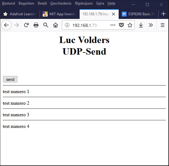
This is how it looks on your computer screen when you have pressed the button a few times.

App inventor program to receive data over UDP

Start a new project in App-Inventor and design the screen as follows:


Not much to it.

We put the UDP extension in the screen and then it appears as an invisible component in the APP. and there is just a label on the screen which uses a large font.

The last component is again an invisible component: clock


The program starts with initialising a global variable with the name var1

The next part is a test wether some information is received over UDP.
If that is the case the label's text is changed into the received information, and the received information is cleared.

Then there is a last block testing the clock.
The clocks timer is automatically set to 1 second. So every second this block is triggered. The variable var1 is incremented with 1 and a message consisting of the word 'test'and the value of the variable is send over UDP to the ESP.

Looking at the ESP's program you can see that there is no routine for receiving anything.
So why should you send something to the ESP.

Actually this is a flaw (bug) in the UDP extension.
For one reason or another you need to trigger UDP communication by sending something to the ESP. Mind you this is a bug in the UDP extension for Android because as you might recall (or re-read) such an action is not needed in ESP to ESP communication.


And this is what can bee seen on your phone's or tablet's screen after you pressed the button on the ESP several times.

Last step is to combine the send and receive part.

ESP program to send and receive UDP packages

We already covered this in the orevious stories when we had two (or more) ESP8266's communicating with eachother. So re-read these stories here XXXXXXXXXXXXXXXXXXX and here XXXXXXXXXXXXXX

 ' UDP send and receive  
 ' written by Luc Volders  
 ' http://lucstechblog.blogspot.nl/  
   
 wprint |<h1 style="text-align:center;">Luc Volders</br>UDP-Send</h1>|  
 wprint "<br/><br/>"  
   
 count = 0  
   
 udpbegin 5001  
 udpbranch [udpreceive]  
   
 button "send" , [sendudp]  
 textbox receive  
 wait  
   
 [sendudp]  
 count = count + 1  
 countst = str(count)  
 mess = "test numero " & countst  
 udpwrite "192.168.1.67", 5001, mess  
 print mess  
 wait  
   
 [udpreceive]  
 receive = udpread()  
 if receive = "Just Luc" then  
 wprint "."  
 else  
 print receive  
 endif  
 return  

Lets have a brief look at the program.

udpbegin 5001
udpbranch [udpreceive]

This sets the port on the ESP8266 to 5001 and jumps to the routine "udpreceive" when some data is received.

button "send" , [sendudp]
textbox receive

When the button is pushed the program jumps to the UDP "sendudp" routine. And the textbox is just there to display anything that is received by the "udpreceive" routine.

The "sendudp" is the same routine we used in the send-only program.

The "udpreceive" routine examins what is being received from your Android Phone or Tablet. If it receives the phrase "Just Luc" it prints a dot "." on the screen. Else it puts the information that is received in the variable receive which will put it in the textbox.

Why the test for "Just Luc" (you can and will alter this for something significant for yourself) you might ask.
Remember the clock function in the Android program that sends every second a UDP package. Well we just test what it sends and if that is "Just Luc" it is irellevant so it will just print a ".". Alter this to your own needs in your project.

Android Program to send and receive UDP packages.

The Design part is simple.


Just a Label which will display the received text. Give it a large font, and maybe a fancy color.
And a button that will send dome data when pushed.

The block section is also not too complicated. it is just a mix of the previous send and receive programs.


First part is when a UDP package is received. The program will put whatever is received into the Text Label.

The clock part will send a UDP package everytime it is activated (every second) and sends the phrase "Just Luc" which will be filtered out in the ESPBasic program as described above.

When you click the button the global variable var1 will be incremented in value and the text "Luc sends text number " with the global var1 will be send to the ESP.

Adapt the clock and the button program parts so they use the IP number of your ESP8266 instead the number I filled in.

That's all folks.

Real life sending and receiving.


This is what the Android program will look on your phone's or tablet's screen.
As you can see it has received two times a data package from the ESP8266


This is what the ESP8266's screen will show you.

Everytime "Just Luc" is received a dot is printed next to the line where the last information was printed.

When you push the send button the text "test numero x" is printed and everytime the ESP receives real data the line "Luc sends test number X" is printed.

Summarising

I do not expect you to use this to send simple text messages from one device to another. The described programs can easily be adapted to send sensor data like temperature, buttons, movement, color codes for leds, slider values for motors etc. etc. etc.

Next to that we have a complete communications suite now for sending data between ESP8266's, Raspberry Pi's and Android Phone's or Tablets.

I bet you can come up with something usefull for this. Do not hesitate to mail me about your projects.

Till next time.
Have fun

Luc Volders

Friday, March 15, 2019

UDP Communication part III ESP to Raspberry

For an index of all my stories click this text

This is the third installment about UDP Communication between wifi enabled devices.

In the first two stories I showed you how to send data using UDP between two ESP's. Re-read that story here: http://lucstechblog.blogspot.com/2019/03/udp-communication-part-1.html
The second story showed you how to send data between multiple ESP's. Re-read that story here: http://lucstechblog.blogspot.com/2019/03/udp-communication-part-ii.html
Both stories showed you also a way to check wether the data was really received. And in both stories the communication was direct between the ESP's without a server or a cloud service for the communication.

It is easy to imagine that you need something more powerfull to process all data that is send between ESP's. Suppose that you want to build a home automation system with a central computer that processes all data. An ESP would probably not be sufficient to control all processes.

In comes the Raspberry Pi.


You could even use the humble Pi Zero for this purpose. The Pi Zero itself is dead-cheap (around 5 euro / 5 USD) and a complete setup with an SD card, powersupply and USB-Ethernet adapter will set you back below 25 euro/USD with some carefull sourcing. This means that for about 25 euro/dollar you can have a full blown Linux computer that controlls your automation processes.

If you want more processing power the Raspberry Pi 3 or 3B offers that for around 35 Euro / USD and offers the advantage that you do not need an USB ethernet adapter due to its build in Ethernet.

Besides that the Pi is easily programmable with Python and loads of drivers and documentation are readily available.

ESP-hardware

For the testing purpose you can use the setup from the previous stories. I am just using a plain ESP-8266 (NodeMCU) with no attached hardware. The test software puts two buttons on a web-page and a slider. That is all.

You can modify the software easily to send all kinds of data like button readings, temperature, motion etc etc etc.

Finding IP adresses.

To get this to work you will need to know the IP adresses for the Raspberry and the ESP8266. The Raspberry's IP adress can be looked up in the Raspberry itself as I'll show you later on in this story.

The IP adress of the ESP8266 is a bit trickier to find. You will have to get into your router to find it.

In my router there is a page that looks like this:
 

In the lower section you can see all the wired devices. And hey there is the Raspberry. So you can also use this to find the Raspberry's IP adress.
In the upper section you can see two devices. The first is my ESP's thermometer and the second is the ESP we are looking for.


The ESP side of the software.

I am using almost the same software as I used in the first and second story. I just added a slider. The program is written in ESP-Basic my favorite rapid devellopment environment.


 ' UDP send data with feedback demo  
 ' written by Luc Volders  
 ' http://lucstechblog.blogspot.nl/  
   
 wprint |<h1 style="text-align:center;">Luc Volders</br>UDP-Sender</h1>|  
 wprint "<br/><br/>"  
 olddimmer = 0  
 udpbegin 5001  
   
 button "on", [on]  
 wprint "<br>"  
 button "off", [off]  
 wprint "<br>"  
 wprint "<br>"  
 slider dimmer ,0,255  
 wprint "<br>"  
 wprint "<br>"  
 textbox rec  
 timer 1000, [sendslider]  
   
 udpbranch [udp.received]  
   
 wait  
   
 [on]  
 udpwrite "192.168.1.78", 5001, "on"  
 wait  
   
 [off]  
 udpwrite "192.168.1.78", 5001, "off"  
 wait  
   
 [udp.received]  
 rec = udpread()  
 return  
   
 [sendslider]  
 if dimmer <> olddimmer then  
 udpwrite "192.168.1.78", 5001, "slider " & "00" & str(dimmer)  
 olddimmer = dimmer  
 endif  
 wait  


Let's have a brief look at the program.

The program starts with the declaration of the variables and the building of the webpage with 2 buttons and a slider.

timer 1000, [sendslider]

udpbranch [udp.received]

These two statements are important in this section. The first (timer) jumps to a routine that makes sure that every second (timer 1000) there is a test wether the slider has changed.
The second statement makes sure that a routine is called that updates the textbox on the screen which is a check wether the UDP command is actually received by the Raspberry.

[on]
udpwrite "192.168.1.78", 5001, "on"
wait

This simply sends the "on" command to the Raspberry. You will need to alter the IP adress in the IP adress of the Raspberry.
Almost the same routine is made for the "off" command.

[sendslider]
if dimmer <> olddimmer then
udpwrite "192.168.1.78", 5001, "slider " & "00" & str(dimmer)
olddimmer = dimmer
endif
wait

This routine sends the slider value to the Raspberry. Again exchange the IP adress for the adress of your own Raspberry.

if dimmer <> olddimmer then
olddimmer = dimmer

This is a clever mechanism in this routine that checks wether the value of the dimmer has altered. When it has been altered the new value is send to the Raspberry. There is no need to send the value if it is not altered.

This is just a framework. Adjust it to your own needs for sending the values you want to send to your Raspberry.


And this is how it looks on your screen. 

As you can see the textbox shows the information (slider 00104) that has been send to the Raspberry and which the Raspberry has send back as a check.


The Raspberry side of the software.

First point your mouse at the top-right side off the Raspberry screen. There is the Panel item for Ehernet.


Click on it and it will reveal the Raspberry's IP adress. Like described earlier you can also find the IP adress in your router. You can fill that in, in the ESP-Basic program described above.

On the following web-page you can find all documentation for UDP communication with Python.
https://wiki.python.org/moin/UdpCommunication#Receiving


I am still using the Geany editor instead of the Thonny editor. Thonny is preferred by the Raspberry Organisation so I should switch. However Geany still accepts Python 2 code which Thonny refuses.


import socket

UDP_IP = "192.168.1.78" # Pi's own IP-Adres
UDP_RETURN = "192.168.1.79" # IP adres from sender
UDP_PORT = 5001

sock = socket.socket(socket.AF_INET, # Internet
                     socket.SOCK_DGRAM) # UDP
sock.bind((UDP_IP, UDP_PORT))

while True:
    data, addr = sock.recvfrom(1024) # buffer size is 1024 bytes
    print "received message:", data
    sock.sendto(data, (UDP_RETURN, UDP_PORT))

I just copied the UDP receive program from that page and made some alterations.

import socket

This line speaks for itself. It just imports the UDP library.

UDP_IP = "192.168.1.78" # Pi's own IP-Adres
UDP_RETURN = "192.168.1.79" # IP adres from sender
UDP_PORT = 5001

UDP_IP is the Raspberry's own IP adress which you just found.
UDP_RETURN is the IP adress of the ESP8266. You can find that in your router as described before.

while True:
    data, addr = sock.recvfrom(1024) # buffer size is 1024 bytes
    print "received message:", data
    sock.sendto(data, (UDP_RETURN, UDP_PORT))

This is where all the magic happens.

while True:

This simple line makes sure that the program keeps running indefinitely

data, addr = sock.recvfrom(1024)

This line sets the variable data to the information that is received over UDP.

sock.sendto(data, (UDP_RETURN, UDP_PORT))

And this line sends the confirmation back to the ESP so we know for sure that the data has been received.

The program is written in Python 2. If you want to use Python 3 you will have to change this line:

    print "received message:", data

Into this:

    print ("received message:", data)


Here you can see the output. I have changed the slider a few times and pushed the ON and OFF buttons on the screen. The information is received by the Raspberry and on the ESP webpage you can check that the information indeed has been send back as a confirmation.


Expansion

Like I said this is just a framework. To make this usefull you would need to expand the ESPBasic program as well as the Raspberry's Python program.

On the ESP side there should be some action when the command is not received back, or mutilated. You could send it again. In any case you should take action.
You could also send an identification with the data so the Raspberry woud know from which ESP the data is coming.

On the Raspberry side we should make a nice graphical page with all the received information.

sock.sendto(data, (UDP_RETURN, UDP_PORT))

This line can easily be altered to send all kinds of information to multiple ESP's. Just alter the data and the UDP_RETURN in the right ESP's IP adress and that's it.

Well that sums it up. It was easier to get the two platforms to talk to eachother as I had expected. My setup worked immediately.

Rests only one thing: Getting my Android Phone to talk over UDP to the ESP and to the Raspberry.

For now a good setup to get things starting.

Till next time
Have fun

Luc Volders

Friday, March 8, 2019

UDP Communication Part II

For a complete index of all my stories click this text

This is the second installment on UDP communication with the ESP8266

In the first story you can read how to send information between two ESP's without using a cloud service or a dedicated local server (like MQTTT). You can read that story here: https://lucstechblog.blogspot.com/2019/03/udp-communication-part-1.html

In this story I am going to show you how to communicate between multiple ESP's. I am setting up 2 ESP's with a switch and 2 led's. And one ESP as the master controller with 4 leds and 2 switches.

The goal is that when you push a button on the master ESP a led will go on at one of the 'slave' ESP's. That ESP will send feedback which will set the control led on the master on. Each of the two 'slave' ESP's has a button. When that one is pressed the other led on the slave will go on and the other control led will go on at the master. This way you can locally see on the slave which led is ON and you can see on the master which leds on all the slaves are ON.

The hardware


The hardware setup is easy. A nodeMCU with two buttons and 4 led's as the master and two NodeMCU's each with 2 leds and a button as the slaves. The two slaves have identical hardware setups.


And this is how it looks in real life.

The software.


' UDP send data demo
' written by Luc Volders
' http://lucstechblog.blogspot.nl/

wprint |<h1 style="text-align:center;">Luc Volders</br>UDP-Sender</h1>|
wprint "<br/><br/>"

io(po,d5,0)
io(po,d6,0)
io(po,d7,0)
io(po,d8,0)

press = 0
press2 = 0

interrupt d3, [butpress]
interrupt d4, [butpress2]

udpbegin 5001
udpbranch [udp.received]

button "on1", [ledon1]
wprint "<br>"
button "off1", [ledoff1]
wprint "<br>"
button "on2", [ledon2]
wprint "<br>"
button "off2", [ledoff2]
wprint "<br>"
wprint "<br>"
wprint "information returned "
textbox repl

wait

[ledon1]
udpwrite "192.168.1.78", 5001, "on 1"
wait

[ledoff1]
udpwrite "192.168.1.78", 5001, "off 1"
wait

[ledon2]
udpwrite "192.168.1.77", 5001, "on 2"
wait

[ledoff2]
udpwrite "192.168.1.77", 5001, "off 2"
wait

[udp.received]
repl = udpread()

if repl = "on 1" then
io(po,d5,1)
endif
if repl = "off 1" then
io(po,d5,0)
endif

if repl = "on 1a" then
io(po,d6,1)
endif
if repl = "off 1a" then
io(po,d6,0)
endif

if repl = "on 2" then
io(po,d7,1)
endif
if repl = "off 2" then
io(po,d7,0)
endif

if repl = "on 2a" then
io(po,d8,1)
endif
if repl = "off 2a" then
io(po,d8,0)
endif

return

[butpress]
press = 1 - press
if press = 1 then
  udpwrite "192.168.1.78", 5001, "on 1"
else
  udpwrite "192.168.1.78", 5001, "off 1"
endif
delay 200
interrupt d3,[butpress]
wait

[butpress2]
press2 = 1 - press2
if press2 = 1 then
  udpwrite "192.168.1.77", 5001, "on 2"
else
  udpwrite "192.168.1.77", 5001, "off 2"
endif
delay 200
interrupt d4,[butpress2]
wait


First let's have a look at the sending software for the master ESP.

io(po,d5,0)
io(po,d6,0)
io(po,d7,0)
io(po,d8,0)

I start with setting the led's off by writing 0 to the io ports.

interrupt d3, [butpress]
interrupt d4, [butpress2]

Next 2 interrupts are attached to the two buttons. The buttons are connected to D3 and D4 and I attached a 10k pull up resistor to them to make sure the level is HIGH when the button is not pressed.

udpbegin 5001
udpbranch [udp.received]

UDP is started on port 5001 and a branch is created that checks wether any information is coming from one of the 'slave' ESP's.

The last part of the setup draws 4 buttons on the screen and a textbox.

When one of the buttons on the screen is pressed an ON or OFF command is send to one of the 'slave' ESP's in the [ledon] and [ledoff] routines.

When one of the real buttons is pressed the interrupt is triggered.

[butpress]
press = 1 - press
if press = 1 then
  udpwrite "192.168.1.75", 5001, "on 1"
else
  udpwrite "192.168.1.75", 5001, "off 1"
endif
delay 200
interrupt d3,[butpress]
wait

If the interrupt is triggered like in the above snippet the variable press is inverted. When it is 1 it will become 0 and visa versa. that is what the line press = 1 - press does. Simply said the line makes the button a toggle button.


Make sure you replace the IP numbers with the IP numbers of your slave unnits.

The udpwrite line sends the information to the selected 'slave' and a small delay is initiated to make sure we wait till the information has been send. And then the interrupt is re-initiated.

When the information has been send the receiving ESP will send a confirmation back. That is received by the [udp.receive] routine. In this routine the incoming information is checked and as a visible feedback a led is set ON or OFF as confirmation.


' udp receiver demo
' written by Luc Volders
' http://lucstechblog.blogspot.nl/

io(po,d6,0)
io(po,d7,0)
press = 0

wprint |<h1 style="text-align:center;">Luc Volders</br>UDP-Receiver</h1>|
wprint "<br/><br/>"

wprint "who send information "
textbox remote
wprint "<br>"
wprint "what was received"
textbox whatreceived

interrupt d3, [butpress]

udpbegin 5001
udpbranch [udp.received]
wait

[udp.received]
rec = udpread()
remote = udpremote()
whatreceived = rec

if rec = "on 1" then
  io(po,d7,1)
endif

if rec = "off 1" then
  io(po,d7,0)
endif

udpreply rec

return

[butpress]
press = 1 - press
if press = 1 then
  io(po,d6,1)
  udpwrite "192.168.1.79", 5001, "on 1a"
else
  io(po,d6,0)
  udpwrite "192.168.1.79", 5001, "off 1a"
endif
delay 200
interrupt d3,[butpress]
wait


The software for the 'slave' ESP's is almost identical although there is a bit less hardware: just 2 leds and one button.


[butpress]
press = 1 - press
if press = 1 then
  io(po,d6,1)
  udpwrite "192.168.1.77", 5001, "on 2a"
else
  io(po,d6,0)
  udpwrite "192.168.1.77", 5001, "off 2a"
endif
delay 200
interrupt d3,[butpress]
wait

The button press routine is the same one as the one on the 'master' ESP

The button works as a toggle button and sets the led on the breadboard on or off and sends the ON or OFF information to the 'master' ESP. The delay makes sure that nothing happens until the info is send and the interrupt is re-initiated.


And also note here that you have to replace the IP number with the IP number of your master ESP.

[udp.received]
rec = udpread()
remote = udpremote()
whatreceived = rec

if rec = "on 2" then
  io(po,d7,1)
endif

if rec = "off 2" then
  io(po,d7,0)
endif

udpreply rec

return

The [udp.received] routine listens for information coming from the 'master' ESP and accordingly sets the other led ON or OFF.


Summarising:

On the master ESP we have two buttons that send information to the slave ESP's which activates a led on the choosen slave. That is confirmed by a control led on the master. When the on the slave itself the button is pressed a signal is send to the master that sets the other led for that slave ON or OFF.

On the slave ESP we have two leds. One is controlled by the local button and when that is pressed a signal is send to the master which there triggers a control led. The second led on the slave is controlled by the master.

This way we have 2 led's on each slave. One is controlled locally and the other is controlled by the master ESP.

Ideas and sidenotes.

UDP communication is easy and you can have one master sending commands to lot's of slaves. A simple home automation controller can be build with this. That is practical But how about devellopping a game with this. Or replace your easter eggs with ESP's. Or build an intruder alarm with several slaves each with a PIR or radar module that can locate the intruder. A remote controlled car in which a master with some buttons sends speed and directions to a slave that controls the motor is another possibillity. Use your imagination.

The UDP communucation works with strings. So do not forget to covert your sensor values to strings when sending them over UDP.

I bet you can build a project with this which I did not think off.

Till next time
Have fun

Luc Volders

Friday, March 1, 2019

UDP Communication part 1

For a complete index of all my stories click this text

There are times / circumstances that you want to have two (or more) ESP8266's communicating with eachother. For example you put an alarm on a door or window attached to an ESP8266. When the door or window is opened it will send a message.

Another example is an ESP8266 attached to a Dallas DS18B20 thermometer that sends an alarm-message when a critical temperature is reached in a server room.
Or you just want a simple alarm when someone in the kitchen puts his hand in the cookie jar. Attach a vibration sensor to an ESP8266 and have it send a message.

That message can be send into the cloud to IFTTT, Thingspeak or Dweet or whatever. For you to see the alarm you will need to have access to a PC or at least a smart phone. Now suppose you do not have that always at hand and you want just a led to blink or a buzzer to alarm you. Wouldn't it just be nice to have the alarm-esp send directly a message to another ESP that blinks a led or sounds a buzzer when it receives the alarm message.

And actually you can. You can have two or more ESP-8266's communicate with eachother without the need of a server or cloud-based service. The communication method is called UDP.

UDP communication

UDP stands for User Datagram Protocol. It is one of the basic communication protocols of the internet. UDP is designed for fast communication between two devices. The reason why it is not always used is that there is no guarantee that the receving device actually has received the message. Another protocol called TCP actually waits till the package is received. And when it is not it will re-send the package until it is acknowledged that the packet is received. UDP just sends the package and that's it.

The good part is that we can actually write or own safety protocol to make sure the packages have been send and received. I'll show you how to do that later on in the story.

The first hardware setup

I'll start easy with 2 ESP8266's. I use the NodeMCU version as that has a connection for USB programming and power supply. You can use the Wemos version to and you could even use the ESP-01.


The first ESP is just powered and nothing further. The seond ESP has a led attached to D7

The first program

My apologies for the diehard c-coders and Arduino afficionado's I am going to do this in my favoritie rapid devellopment environment: ESP-Basic. If you are not familiar with ESP-Basic I urge you to read this introduction story which will help you setup your ESP and help you start programming in no-time:
http://lucstechblog.blogspot.nl/2017/03/back-to-basic-basic-language-on-esp8266.html

Let us start with sending an UDP message.

The first thing to do in ESP-Basic is to tell the interpreter on which wifi-port the UDP communication is going to take place. Port 80 is normally used for HTML communication. UDP is generally done on port 5001. However feel free to use another port.

The second thing is to actually send the message. However you need to know to which IP adress you are going to send the message.


So open your router and look for the two ESP's. As you can see in my Zyxell router they are found with the names ESP_XXXXX. Clicking on these icons reveals their IP'adresses.

So now we have the information compleet we have the basic information to send UDP messages. In ESP-BASIC we just need two lines to send a message:

udpbegin 5100

udpwrite "192.168.1.78", 5001, "on"


This will send the message "on" over port 5001 to IP-adress 192.18.1.78.
You will need to replace the IP adress with your own.

Receiving the message on the other ESP-8266 is a bit more complicated.

First we need to start udp communication by defining a port over which the messages are send. We can use the same port or another one. The used port is for this particular ESP. I used the same portnumber:

udpbegin 5001

Now we need to tell the ESP what to do when a message is received. We need to do that by making a udpbranch which is basically a jump to a subroutine. You can name that routine anything you like. I called it udp.received

udpbranch [udp.received]

Now we need to build the actual routine that acts when a message is received:

[udp.received]
rec = udpread()

if rec = "on" then
  io(po,d7,1)
endif

if rec = "off" then
  io(po,d7,0)
endif

return


This is straightforward.
We declare a variable called rec (abbrevated from received) and put whatever is received over udp in it.

Next we test if the message received was "on" or "off" and accordingly set IO port d7 on or off, resulting in the led getting on or off.


' UDP send data demo
' written by Luc Volders
' http://lucstechblog.blogspot.nl/

wprint |<h1 style="text-align:center;">Luc Volders</br>UDP-Sender</h1>|
wprint "<br/><br/>"

udpbegin 5100

button "on", [ledon]
wprint "<br>"
button "off", [ledoff]
wprint "<br>"
wprint "<br>"

wait

[ledon]
udpwrite "192.168.1.78", 5001, "on"
wait

[ledoff]
udpwrite "192.168.1.78", 5001, "off"
wait

So here is the complete listing for the Sending ESP


' udp receiver demo
' written by Luc Volders
' http://lucstechblog.blogspot.nl/

wprint |<h1 style="text-align:center;">Luc Volders</br>UDP-Receiver</h1>|
wprint "<br/><br/>"

udpbegin 5001
udpbranch [udp.received]
wait

[udp.received]
rec = udpread()

if rec = "on" then
  io(po,d7,1)
endif

if rec = "off" then
  io(po,d7,0)
endif

return


And here the complete listing for the receiving ESP


This is how it will look on your screen when you open two browser windows each pointing to the IP number of one of the ESP's.


And this is how it looks in real life. On the right side is the sending NodeMCU and left the receiving one.

Just push the "on" button on the screen and on the receiving ESP the led will go on. Push the "off" button and on the receiving ESP the led will go off.
It's that easy to have a complete communication between two ESP8266's.

Experiment with this a bit before we go on to the next step.

Checking communication

As you have seen in the previous example the UDP message is send and we can only hope that it is received on the other side. So let's build a check into our receiving program.

wprint "who send information "
textbox remote
wprint "<br>"
wprint "what was received"
textbox whatreceived

To check what is received we can put a textboxes on our screen that will be filled with the information. I put 2 textboxes on the screen. The first displays what IP adress the information was received from, and the second displays what information was received.

Further there is a build-in option that just resends the received information back to the original sender. So in the receiver program we just have to put the following lines:

[udp.received]
rec = udpread()
remote = udpremote()
whatreceived = rec

if rec = "on" then
  io(po,d7,1)
endif

if rec = "off" then
  io(po,d7,0)
endif

udpreply rec

return

The variable rec is filled with the information that is received. The variable remote gets the IP adres from the sender. And the variable whatreceived is copied from the variable rec so the textbox gets filled.

The critical line here is:

udpreply rec

This simple line sends the information received back to the original sender !!!

Now we only have to alter the UDP-send program in such a way that it receives the information back as a check that everything went ok.

Basically this is the same as the lines in the receiver software. So in the UDP-send program we start with a test wether information was received over UDP (the reply from the receiver) :

udpbranch [udp.received]

That information will be displayed in a textbox:

wprint "information returned "
textbox repl

And we need to make the routine where the information which is send back is put into a variable:

[udp.received]
repl = udpread()
return

And that completes our UDP-send program with a feedback that checks if the send information is really received and processed.

' UDP send data demo
' written by Luc Volders
' http://lucstechblog.blogspot.nl/

wprint |<h1 style="text-align:center;">Luc Volders</br>UDP-Sender</h1>|
wprint "<br/><br/>"

udpbegin 5100
udpbranch [udp.received]

button "on", [ledon]
wprint "<br>"
button "off", [ledoff]
wprint "<br>"
wprint "<br>"
wprint "information returned "
textbox repl

wait

[ledon]
udpwrite "192.168.1.78", 5001, "on"
wait

[ledoff]
udpwrite "192.168.1.78", 5001, "off"
wait

[udp.received]
repl = udpread()
return

So above is the complete UDP-send program


' udp receiver demo
' written by Luc Volders
' http://lucstechblog.blogspot.nl/

wprint |<h1 style="text-align:center;">Luc Volders</br>UDP-Receiver</h1>|
wprint "<br/><br/>"

wprint "who send information "
textbox remote
wprint "<br>"
wprint "what was received"
textbox whatreceived

udpbegin 5001
udpbranch [udp.received]
wait

[udp.received]
rec = udpread()
remote = udpremote()
whatreceived = rec

if rec = "on" then
  io(po,d7,1)
endif

if rec = "off" then
  io(po,d7,0)
endif

udpreply rec

return

And here is the complete UDP-receive program.


And this is what it looks on your screen.

Just open a separate browser window for each ESP and you can see what is happening.

There you have it.
A basic setup for you to play with and enough information to send data between two ESP's without the need for a cloud service or dedicated server.

Next time things get a bit more complicated as I am going to use 3 ESP's. One as a controller and two to switch lamps locally and remote.

Till next time
have fun

Luc Volders