Friday, July 30, 2021

Blynk: A sad story

 For an index to all my stories click here

Something bad has happened.

As you know I published several tutorials about Blynk on this weblog. You can find the last story, which has references to the previous ones, here: http://lucstechblog.blogspot.com/2021/06/blynk-part-4-using-blynk-with-multiple.html

Blynk is of-course not new. It started several year ago as a Kickstart project and has evolved to a IOT system that is used by many users world-wide.
Now the makers of Blynk have released a new version. This version called Blynk 2.0 is not compatible with the old versions, and has a different billing system.

Normally that would not bother and upset me too much. But this is different.

In the old Blynk you could use several ESP's on their server for free until you used all your free energy points. Then you could buy energy points from the Blynk company or take a different approach.
The different approach was to start your own Blynk Local server. That could easily be done with a Raspberry 3. The software was free to get and that made this a cheap solution. And it would give you all the free energy you needed to build hundreds of IOT projects.

The new Blynk only allows you to use 1 ESP. If you need more then you have pay a fee for each one. Worse is even that there is no free software to build your own server. So this is a much more expensive solution.

No worries though, we keep using the old Blynk and the local server.


Well this is where the bad part happened.


The company that founded Blynk has removed the software for building your own server from Github.


If you look for the Blynk server using the link I provided in my story it provides you with the above picture telling that the page does not exists anymore.

This is really a shame. Not only that, it is bad policy. Everyone who build projects and applications with Blynk and wants to expand has to move over to the new version and re-program all their hardware devices.

What they should have done is leave the old version in existance. Just tell the users that they can still use the old version but at their own risk. That there will be no service and updates anymore, but you can keep using it.

Fortunately I had seen this coming.
Blynk is next to a commercial company also an open source project which was published under the GNU-GPL license.
So I made a fork of the Github pages.

Anyone looking to start their own Blynk server based on Blynk V1.0 like discussed in my stories can find the repositry here: https://github.com/Lucvolders/blynk-server

Please also make sure that you keep on using the legacy Blynk app and do not by incidend update the Arduino libraries. The new Blynk libraries will only work with the new Blynk APP.

So Blynk V1.0 is no longer maintained and therefore there will be no future updates anymore. If you want to install the Blynk local server and use the old version do so at your own risk. If you are already running a local server it will keep on working.

Like said before I still have some projects with Blynk coming up. And keep reading this web-log as I am examining alternatives for Blynk to use in the future.

Till next time.
Have fun

Luc Volders


Friday, July 23, 2021

Build your own button caps

For an index to all my stories click this text

I needed some square push buttons for a project. They had to be around 2 x 2 cm and off course I did not have those in stock.


I do have a large pile of tactile buttons that measure 1 x 1 cm and have a round cap. The buttons would do fine, but the caps were round and too small. So I started searching the internet.

I found a replacement cap for my tactile buttons but that was also round and too small. And then I found a nice square cap. Unfortunately the size was too small and it was made for a different push button so it would not fit.

Tinkercad to the rescue.


I started with importing the square tactile button.


I resized it to the size I needed and then cut out the part that connected the cap with the button.


Next I imported the round button.


Next step was to make a hollow tube that was about the diameter of the round cap.


Merging the two would cut away the edge of the round button so only the middle part would be left over and that is the part I needed.


I moved the inner part of the round cap into the square cap.


The last step was to adjust the hight of the square cap to the right hight and merge the two items.


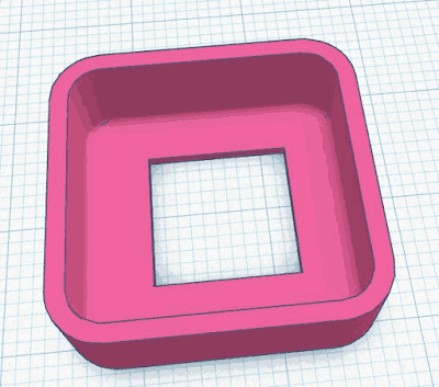
And here is the result. I printed the cap in different colors to see which one would be best for my project. The last picture shows how big they are compared to the original round caps.


I printed an extra 3 pieces in white PLA and then painted them with bronze, silver and gold acrylic paint. This was the first time I painted any of my 3D prints. I had to put 3 layers of paint on them to get the best coverage and I think they came out rather well. The picture does not do justice, in real life they look much better !!!

If you want to print these for your own purposes. Here is the link:
 https://www.tinkercad.com/things/7PGkLoa9JoA


Till next time.

Keep tinkering and have fun !!

Luc Volders

Friday, July 9, 2021

Universal code for ESP8266 and ESP32

For an index to all my stories click this text

You might stumble upon the same problem I encountered. You are building a project and are not sure wether an ESP8266 is sufficient or have to switch to an ESP32 later on.
This post is about building software which automatically detects on which ESP it runs and adjusts its parameters. Let me explain why I needed this.

Lately I have been involved in a large project. My Son in law asked me to assist in building an aquaponics system. He is doing the mechanics and I am to build the electronics.
As we are at this early stage not sure how many sensors and actuators we are going to use in the end.  I started the project with an ESP8266. We might need an ESP32 however, due to its extensive IO ports.

This gives me two possibilities. I can rewrite the code when we swicth from the ESP8266 to an ESP32, or I can structure the program from the beginning on to be ready for both controllers.

Naturally I opted for this last possibility and this is how to do that. I am using the Arduino IDE (C++) for programming the ESP's.

#if defined()

This is the magic command that makes it possible to write universal code.

When you write C++ code and upload it to the Arduino or ESP it is compiled. Hardcoded in this compiled code is included for which processor the code is. This way a program written for the ESP32 will not run on an ESP8266 and the other way roud. This makes perfect sense as both are from the same family however use different libraries and pinouts.

The question is how we can use that information. And as a matter of fact it is really easy.


#if defined(ESP8266)
  SOME ESP8266 CODE
#elif defined(ESP32)
  SOME ESP32 Code
#endif

Put this at the beginning of your program and these lines make sure that the code for the right processor is loaded.

How can we set this to work for us.

Lets start with something that looks simple and actually is aq bit more complex as you think. But let it not set you off as it will be clear in the end.

Let's start with a simple blink program.

#if defined(ESP8266)    
    int led = 05;  // GPIO D1 on ESP8266
#elif defined(ESP32)
    int led = 22; // GPIO22
#endif

void setup() 
{
pinMode(led, OUTPUT);   // Initialize the LED pin as an output
}

void loop() 
{
digitalWrite(led, LOW); // Turn the LED on
delay(1000);                // Wait for a second
digitalWrite(led, HIGH);// Turn the LED off
delay(1000);                // Wait for a second
}

And here you can see how it is done:

#if defined(ESP8266)    
    int led = 05;  // GPIO D1 on ESP8266
#elif defined(ESP32)
    int led = 22; // GPIO22
#endif

If the compiler notices that the program is for the ESP8266 the code in the #if will be compiled giving the led variable a value of 5 which is pin 5 also known as D1 on the ESP8266.
However if the compiler notices that the program is written for the ESP32 the code in the #elif will be compiled.

Hey, wait. We are not using the pin numbers usually when coding for the ESP8266. Normally you will use D2 (or another pin of your liking). Alas that will not work. If you would put that in your program the compiler would forget the D and use pin 2 which is at board number D4 (trust me, I've been there). So we need to make a refernce to the actual pin numbers.

 1
 2
 3
 4
 5
 6
 7
 8
 9
10
11
12
13
14
15
16
17
18
19
20
21
22
23
24
25
26
27
#if defined(ESP8266)    
    // Assign Arduino Friendly Names to GPIO pins
    #define D0 16
    #define D1 5
    #define D2 4
    #define D3 0
    #define D4 2
    #define D5 14
    #define D6 12
    #define D7 13
    int led = D2;  // IO port D2
#elif defined(ESP32)
    int led = 22;  // GPIO22
#endif

void setup() 
{
pinMode(led, OUTPUT);   // Initialize the LED pin as an output
}

void loop() 
{
digitalWrite(led, LOW); // Turn the LED on
delay(1000);            // Wait for a second
digitalWrite(led, HIGH);// Turn the LED off
delay(1000);            // Wait for a second
}

And there we are. We referenced the IO pins to the D-numbers on the board and now we can use the D-numbers like we are used to. I have tested this with a NodeMCU board and a Wemos-D1.


For reference I give you here the ESP8266 pin layout for the D1 and NodeMCU boards where you can see the difference between the actual pin numbers and the D-numbers on the board.


At the ESP32 side things are much easier. The D-numbers on the board actually correspond with the GPIO numbers. The Arduino IDE does not use the actual pin numbers which makes life a lot easier.

How about libraries

Indeed there is a difference in libraries for the ESP8266 and the ESP32. We can dissolve this in the same manner.

#if defined(ESP8266)    
    // Assign Arduino Friendly Names to GPIO pins
    #define D0 16
    #define D1 5
    #define D2 4
    #define D3 0
    #define D4 2
    #define D5 14
    #define D6 12
    #define D7 13
    int led = D2;
    #include <ESP8266WiFi.h>
    #include <ESP8266WebServer.h>
    ESP8266WebServer server(80);
#elif defined(ESP32)
    int led = 22;
    #include <WiFi.h>
    #include <WebServer.h>
    WebServer server(80);
#endif

Just look at this part of the beginning of a larger program.

If the program is going to be compiled for the ESP9266 then the compiler will use the ESP8266Wifi.h library and the ESP8266WebServer.h library and then automatically makes an instance for the webserver.

When the program is compiled for the ESP32 the Wifi.h and WebServer.h libraries are installed and again the right instance for the webserver is created.

If you are coding for both ESP versions this will make your life a lot easier.

Till next time

Luc Volders