


I started by testing the ledstrip with batteries. Before messing around with it I needed to be sure that it delivered enough light for my purpose. And yes indeed it was exactly what I sought. As you can see it delivers enough light for a small workspace.
On to the next step.
I wanted the ledstrip to be connected and controlled by an ESP-8266. However the ESP8266 can not supply enough current by itself to control the ledstrip. So I had to do some calculations.
There are 30 leds in the strip. As each led will consume about 20 mAmps the power consumption will be 30 x 20 mAmps is 600 mAmps. So a TIP120 transistor would be more as sufficient for the job. I build a test setup and examined if it would do the job.

As you can see a very simple setup. Just a TIP120 transistor that is attached to the 5 volt power reel and a loose breadboard cable (the green one) which I alternately plugged in the 5Volt and GND lines to see if the ledstrip would switch on. And that worked flawlessly. So the Tip120 was indeed the right choice.
Next step was to make the ESP-8266 do what I wanted.
And what did I want ???
Well I wanted easy access from a website.
I started with the hardware setup. I used a NodeMCU board for testing. The NodeMCU board gives breadboard access to all I/O pins and is easily programmable through its USB interface. The NodeMCU board is a miracle in itself however not really breadboard friendly. I could have used my NodeMCU breadboard aid which you can find by clicking here, but I decided to take the easy way out.

As you can see I only need the left side of the NodeMCU to get my prototype working so I just plugged it halfway into my breadboard. I attached 2 leds to GPIO0 and GPIO2.

Please note that the pinnumbering on the NodeMCU does not correspondent with the GPIO numbering. The pin called D3 is attached to GPIO0 and the pin D4 is attached to GPIO2.
The software
As you can see the software is pretty straightforward. It is written in the standard NodeMCU language: LUA
I chose for the Wifi-Station mode as this gives me access to the software from every computer, laptop, tablet and smartphone in my house, and if I open a port in my router from anywhere in the world.
Do not forget to fill in your own router details in program line 2 if you want to play with this webserver yourself.
Line 5 to 10 define the I/O ports and put them in the LOW state so the leds start in the OFF function.
Line 24 to 37 make the actual webpage. As you can see I just used 2 I/O ports so I made 2 ON-OFF switches on the webpage. You can easily expand this for your own purposes to use all I/O ports on the NoceMCU.
Just don't forget to rename this program in INIT.LUA if you want to start the webserver automatically when the NodeMCU is powered up.
And that is just what you need to do: power up the NodeMCU.
Next step is to get access to your router to see that IP adress the NodeMCU has gotten from your router. I can not tell you how to do this as each router works differently.


As you can see in my setup my router sees an unknown wireless apparatus that is attached. If I ask the details it shows the IP-Adress. This is the way to know how to adress your ESP module from inside your network.

Now if I type the just found IP-Number in my web-browser I will immediately get the above showed web-page. Isn't that just fantastic a complete web-page in about 50 lines program code !!! The ESP-8266 are really marvels.
Let's see if the software works.


Incredible !!! Fantastic. Just a few lines of code and I can switch led's on and off simultaneously from several devices (phone and computer) all accessing the same webpage. It is fully understandable why this ESP-module has so much attention in the tinkerer community.
And on we go to the next step.
Obviously I needed to combine the power transistor TIP-120 with the NodeMCU if I wanted to control the ledstrip over Wifi and here is the breadboard setup.


And there you go. Switching GPIO-0 on and off on the website really switches the ledstrip on and off.
Now there is one final thing to do.
It is a bit overkill to use a complete NodeMCU board for just controlling 1 GPIO pin. It is more efficient to use the tiny ESP-8266-01 for that. There are however a few things to take into consideration.
The ESP8266-01 does not have a USB port. Therefore you will need a FTDI for this. The easy way to achieve this is to build my ESP8266-01 Programming board which you can find by clicking here.
There is however antother small issue and that is that the ESP82636-01 baord works at 3.3 volt. As I was planning to power the complete setup from a 5Volt power adapter (the same one used as phone adapters) I needed to make a step-down power converter. And what is better suited for this as the LM317. You can find detailed information about this voltage regulator by clicking here.

In the story about the LM317 you will find a link to a calculator that gives you the right resistor values for stepping down from 5 volts to 3.3 volts. I used resistor values 1.2KOhm and 2Kohm. If you do not have them at hand you can substiture them (both) for values found by the calculator.


Above you can see the breadboard setup for the LM317 and the breadboard setup for the TIP120 and LM317 combined. There only rests one thing:


For completeness I included the total breadboard setup and schematics with the LM317, the TIP120 and the ESP8266-01. As you can see I used GPIO-0 for controlling the ledstrip.
There is just one small issue that needs to be taken in consideration.
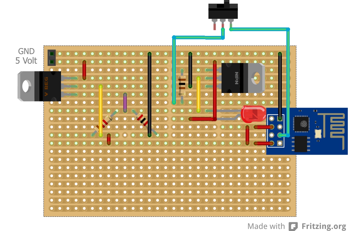
As you can see I added a switch between GPIO-0 and the resistor connected to the TIP120. The reason for this is that the GPIO-0 pin has to be at HIGH level when the ESP is powered up. If that is not the case the ESP switches to program mode which is obvious something we do not want. So you put the switch in the off position when you power up the ESP and after a short while put the switch in the ON position and you are ready to go.
Also DO NOT forget to cut the stripboard leads where it is needed. That is between the two resistors for the LM317, under the ESP8266-01 to separate the left side contacts from the right side and between the LM317 and TIP120 setup and the part that seperates the ESP8266-01 from the rest. Just examine the stripboard and schematics well and you know where to look.

My power supply is as stated before a 5Volt USB power supply. I bought it at the dollar-dollar shop (called Action in the netherlands) and it delivers 2.1 Amps.

The last step was to adapt the software for the use of just one IO pin and I changed the text to something more suitable for the project.
Now the only thing that needs to be done is to make a proper housing. But that is easy if you own a 3D printer like me.
And to give credit to where credit is due: all schematics, breadboard and stripboard drawings were made with Fritzing.
I have more projects with the ESP8266 coming up like a rain detection system that twitters when it is raining. In the end I want to build a complete domotics system, so watch this space.
ESP Ledsptrip controller source code
Disclaimer: check, double check and triple check your stripboard before you attach it to the power. Test each part, LM317 setup, TIP120 setup, ESP8266-01 setup individually before you connect it all together. I take no responsability for blown fuses, burnt down houses or whatever. Be sensible, check my schematics, breadboard layouts and stripboard layouts before you use them and do so on your own risk.
Till next time
Have fun
Luc Volders