For an index to all my stories click this text.
Up until now I have been using Fritzing for all my electronic designs on this weblog. However Fritzing is moving away from a free version to a paid version. And although I realise that not all things in life are free, I hate it when free software suddenly turns into a paid version.
So I started looking for an alternative.
I have discussed Wokwi before on this web-log. You can read that story here: http://lucstechblog.blogspot.com/2022/04/simulate-your-controllers-with-wokwi.html
Wokwi is certainly usefull but has a limited parts library.
Then I stumbled upon Cirkit.
Cirkit is free, has an already large parts library and is easy to use. And just like Fritzing is Cirkit used off-line. Just download the program and start working. Cirkit has next to all that one great feature: it is very easy to create your own parts!!
Check it out, you might actually like it. Here is the link to the website: https://www.cirkitstudio.com/
After downloading and examining the parts-library I instantly missed the Wemos Mini D1 board. As I was doing a project in which In needed a schematic with the Wemos D1 mini board I was put off in first instance. Then I remembered that it was advertised that you can easily add your own parts in Cirkit Designer. So I took that for a test.
Fisrt step is to search for a good high resolution picture of your desired component. High resolution is not per-se needed but the better the picture the better the end-result. So I found a usable picture with Google. The reolution of this one was 800*750. As said bigger is better.
For graphics editing I always use the Gimp. You can find the Gimp here: https://www.gimp.org/ I loaded the picture into The Gimp and made a cutout.
When done I saved the picture as a .PNG picture.
At the left side of the screen in the middle there is a small arrow like symbol. Clicking that will bring out the fold-out menu with all components. At the bottom in Green it says "Create custom Component" click on that.
First step is to give your component an name. I chose Wemos D1 mini
The next step is to define your components pins. Start with loading your components picture by clicking on Select component Picture and import your .PNG image.
Using the + and - at the right side on the botoom of the screen you can enlarge the picture till you get a workable version.
Now click on the leftmost icon (looks like a pushpin).
Count how many pins you will need. The Wemos Mini D1 has eight pins on each side. By pressing the pushpin icon each time a new dot is placed on the screen. Place the 16 pins and line them up.
Click the second icon from the left (Snap to grid) and move the dots a bit. They will automatically be placed at the right distance from eachother.
Click anew on the picture of the Wemos D1 mini. Small squares will appear at the corner of your picture with which you can scale the image.
Enlarge the picture as much as is needed so that the blue dots are lined up with the pinholes in the image. Try to do this as accurate as possible.
In the menu on the left side on the screen scroll down till you see point 4 : Define Component Pins. Click on a blue dot and give it it's pin name.
In the menu scroll upwards and save the new component.
And there it is. In the menu on the left side the new component is shown in the User Defined section. It is now ready to be used on the breadboard.
And as you can see when the component is placed on the breadboard it fits nicely. Clicking on a blue dot directly gives it it's pin name.
If it does not fit just go back to the component on the left side in the User Defined menu. Click on it and choose edit and you can resize it or alter the name or the pin names. Don't forget to save again.
And here is a first breadboard drawing I made with my new component.
It is indeed very easy to design new components in Cirkit designer and this is not the last time on wthis web-log that I will use this program.
Till next time
Have fun
Luc Volders
Friday, August 26, 2022
Create a new component in Cirkit
Friday, August 19, 2022
Make a mold from your 3D prints
For an index to all my stories click this text
In this article I am going to show you how to make a mold from your 3D print. With a mold you can easily make as much copies of your print as you like. The technique shown here can easily be used for your own designs.
Remember the shackleguard I designed and 3D printed ?? You can find that story here: http://lucstechblog.blogspot.com/2022/07/build-shackle-guard.html
Well what if you wanted more as one piece. You could print several of course. That would take a lot of time. So how about making a mold from it and produce as many as you want. That was the idea and I set out to try to realise it.
Building the mold
I started with examining the original shackleguard. It appeared that it was a bit smaller at the top and wider at the base. Give this some thought as that will make it more difficult if not impossible to get out of the mold.
So I selected the rotate tool in Tinkercad
And I rotated the guard 180 degrees. As you can see the top is now wider as the bottom. That will make it easier to get them out of the mold.
Next step was to make a box which is a bit larger as the shackleguard. For convenience give the box a different color.
lift the shackleguard so that the top of it is a bit higher as the top of the box.
Move your model into the box. It is neat if it is centered but no worries if it is a bit off.
Carefully lower the model into the box so the top of both the model and the box are at the same hight.
Turn the model into a hole.
And group the two items.
That's it.
In Tinkercad export the mold as an STL file. Import it in your favorite slicer. I used the Creality slicer as this is not a very complicated model and I sliced it at .3 mm The slicer shows that it will take 1 hour and 36 miniutes to print.
And here is the finished mold !!
Oogoo
Back in 2016 I wrote a story on this weblog about Oogoo. Oogoo is a rubber-like substance made from a mixture of cornstarch and Silicone caulk. This would be ideal for my project. Re read the story on Oogoo here: https://lucstechblog.blogspot.com/2016/04/oogoo-and-oobleck.html
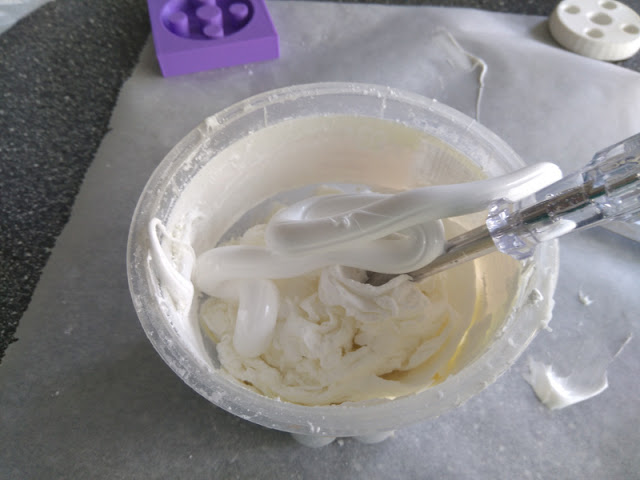
I mixed 2 parts of Silicone caulk to one part of cornstarch. That gives a thick paste. 
The mold was liberally filled with the paste.
I waited a day to let the substance cure then I cleaned the surface of the mold.
And here is the finished product after I got it out of the mold and cleaned it up a bit with a sharp knife. Removing the part from the mold was actually easier as I thought.
This picture shows the original printed version on the right and the Oogoo one on the left. The Oogoo version still needs a bit of cleaning up at the bottom of the holes. but you can see they are identical.
Actually the Oogoo version is better for this purpose as it is more rubbery. It bounces nicely and therefore is ideal as a shackleguard as it will not damage your boat if it hits the boat.
This was more fun as I expected. The oogoo shackleguard could nicely be removed from the mold and the mold can be used to produce some more.
Till next time
have fun
Luc Volders
Friday, August 5, 2022
See you on Discord
For an index to all my stories click this text
By now you must have heard of Discord.

Well maybe you didn't. Discord is a fancy name of what we used to call a forum. It has some extra features like voice-chat. But basically it is like an advanced forum.
The difference is that Discord is not just a forum on just one subject. It is a collection of numerous forums which you can access all at the same time. Subjects vary from entertainment to technical forums. I have joined (until now) several technical servers/communities like Cirkit, Wokwi, B4X, Raspberry Pi Pico and ESP8266/ESP32.

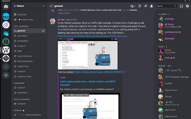
On the left side of the screen there is a line of icons that bring you to the selected forums. The second column gives you all the sections of each individual forum. In the third column you can read and post messages. And the last column shows a list of all members of that particular forum.
Like normal forums you can exchange text and foto's.
And what is more: you can easily build your own forum/community.
And that is what I did.
My community is called LucVolders and if you want to have a look just click on the following link. It's logo is the blue dot at the top with the text "tech" in it. At this moment it is empty. Just feel free to post messages/questions about my web-log or messages and/or photo's from your own projects.
And YES I do moderate so play nice.
https://discord.gg/ustRzPq29H
And discord has something extra called Bot's.
With a Bot you can automate a lot of things. But you can also have your microcontroller send messages to Discord.

The above picture shows that I have send a message with my Raspberry Pi Pico W to Discord. The program to do this was written in MicroPython.
I am planning (and already been doing the research) on writing a book on using Wifi with the Raspberry Pi Pico W. If you are interested just drop a line in my discord server in the appropriate sub-forum.
I don't know yet if I am going to be a long time user of Discord, that also depends on how many of you are joining my Discord channel. However until now it has been fun.
Till next time
Have fun
Luc Volders

