

As a kid I was fascinated by remote controlled cars. I never owned one but several of my friends had one. I did not envy them because just driving around such a car and running after it was not really my idea of fun. It just intrigued me how such a thing worked.
A few years ago when I was building my own 3D printer, just before I really dug into electronics, I started to comprehend how the electronics to control motors and stepper motors work. And now surfing all kinds of technical websites I got interested in remote controlled cars again. How difficult could it be ?? A transmitter, a receiver, a transistor to send a strong current to the motor and you're done. Piece of cake or not ??
Forward is easy
Controlling a motor is one of the fundamental excersises when you start learning Arduino and electronics. An arduino can not provide enough current to control a motor. So you will have to reinforce the signal from the arduino with a transistor. I have done this before on this weblog when I was controlling a ledstrip. The drill is basically the same. So let's look at the most simple setup.

The software only has to put one of the digital outputs to high to get the motor running. Set it to low and the motor stops. So we can go forward and we can stop. How about turns ??
Turning left and right.
Well this is easy to. For strength we will use two motors to drive the car. Turning to the left is easily done by stopping the left motor and running the right one. Turning to the right is just the opposite. Stop the right motor and run the left one.
H-Bridge
So with these simple steps we can go forward, left and right. But we also need to drive backwards. That is more complicated. To get the motor running in the opposite direction you need to switch polarity, and that is easier said as done.
Long time ago a solution was found for this problem and it is called an H-Bridge. Basically at first this was achieved with switches. Just look at the next schematics.

The switch on the top left side is open and the switch on the bottom right side is open. So the cirrent can only pass on the top right side through the motor and then down. The motor therefore runs in one direction.
Now look at the right side.
The switch on the top left side is closed and the one on the bottom right side is closed. Just the opposite of the previous state. In this situation the currect has to flow from the right side through the motor to the left side. And that makes the motor run in the other direction.
This works great. However done with switches it can not be operated remotely. Well actually it can !! and it was done in the early days. I still remember remote controlled cars with a wired remote...... But that is not what we are trying to achieve.
Fortunately electronics come to the rescue.

An electronic H-Bridge can be made by pairs of NPN and PNP transistors.
The electronic H-Bridge works the same way as the mechanical one. The switching is done by a small current send to the base of the transistors. This works because the NPN transistors allow current to flow when the base voltage is high, and the PNP transistors allow current to flow when the base voltage is low.
As you can see this can easily be build by yourself. For two motors you will need two of these circuits.
Let's make things easier.
As running motors is very popular dedicated H-Bridge IC's are widely available.
We are going to use the popular L293D.

As you can see it is easy to use. The IC is build up symetrically, and can control 2 motors at the same time. On the left side there is a VCC connection and in the middle 2 GND pins. Next to the GND are the motor connections and next to that the input pins which can be attached directly to an Arduino, ESP8266 or a Raspberry Pi.
The right side has the same connections mirrorred. So with this you can attach two motors and control them by 4 pins from your microcontroller.
Set one IO port of the controller HIGH and the other LOW and the motor will run forward. Switch the HIGH and LOW and the motor will run backwards.

For completeness I herebye give you the pin layout.
The L293D has some impressive features. It will run motors up to 600Ma and it can drive motors, solenoids and even steppers.
Make sure you opt for the L293D version. This one has clamping diodes that makes extra electronics unnecessary. You can also choose the SN754410 which has the same pinout so can be exchanged 1 on1 in the setup. However the SN754410 can supply a larger current (1A) so can be used for stronger motors.
Speed
Going forward and backward is one thing. But by setting the IO pins to 1 or 0 will just make the motor run at full speed or stop.
What we want is speed control. And that is where PWM comes in.
Luckily all modern micro controllers like the Ardiuino, ESP and even the Raspberry have PWM control. I presume you have used it yourself in your projects to dim a led for example.
For those not familiar with the term. PWM is the digital equivalent of setting the voltage on an IO pin. Normally the pin would be LOW or HIGH. And HIGH will be 5Volt or 3.3Volt depending on your micro controller. By setting the PWM value of an IO pin you can set the output voltage of that pin on any value between LOW and HIGH.
Actually it is a bit more complicated. The PWM function sets the pin alternately HIGH and LOW but in a very fast pace and that makes it look like a certain voltage. That is the theory. In real life for most electronics it looks like a variable voltage and that can regulate the speed of our motors.
Wireless remote control.
Several options come to my mind.
- Attach a bluetooth controller and an LD293D to an arduino and write an app with app-inventor to control it
- Attach 433Mhz transmitter to an arduino and use potmeters to set speed and direction. Use a second arduino with a 433Mhz receiver to control the LD293D. This will give you a larger range.
- Attach a NRF24L01 instead of the 433Mhz version described in the preivious point.
- Attach the LD293D to an ESP8266 and control it from a webpage.
Well to get things up and running fast I choose the easy way out (again). I choose my preferred rapid devellopment tool: ESPBasic. If you have never worked with ESPBasic before I urge you to read my introduction story which you can find here:
https://lucstechblog.blogspot.nl/2017/03/back-to-basic-basic-language-on-esp8266.html
Before we look at the program let us have a look at the hardware setup.

As you can see I attached the L293D motor 1 pins to pin D0 and D1 of the ESP and motor 2 pins to D2 and D4.
For testing purposes (before I mounted everything on a frame) I attached leds to the control pins so I had a visual indication to the direction of the motors. In the finished model I left the leds out. You can leave them in and use them as headlights.

So far for all the theory now is the time to try it out real time. Therefore I used a powerfull powerbank that has 2 USB outputs. The first one supplies max 1 amp and that is attached to the ESP. The second USB output supplies 2 amps and that is connected to the power rail of the breadboard to power the LD293D that directly powers the motors.

The motors and wheels I used are the standard versions that can be bought for a few dollar from your favorite Chinese supplier.

From the local dollar store I bought some cheap caster wheels. The motors are used for the front weels and on the back there is just one caster wheel.
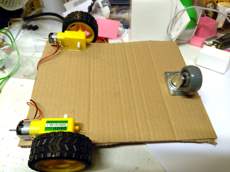
When everything worked as expected I made a square frame from carton. With hot glue I glued the motors to the bottom of the frame attached the wheels and glued at the back the caster wheel.

That's all.
It's not the prettiest of all the remote controlled card but remember this is only a proof of concept.
The program.
io(po,D0,0)
io(po,D1,0)
io(po,D2,0)
io(po,D4,0)
motonedir = 0
motwodir = 0
motone = 500

wprint |<body style="background-color:powderblue;">|
wprint |<H1><span style="color:

red;">|
wprint "Motor Control<br>"
wprint "By Luc Volders"
wprint "</H1>"
wprint "Motor speed"
slider motone, 300, 1024
wprint "<br><br>"
button "Forward", [forward]
wprint "<br><br>"
button "Stop", [motonestop]
wprint "<br><br>"
button "Backwards", [backward]
wprint "<br><br>"
button "left", [leftturn]
wprint "<br><br>"
button "right", [rightturn]
wprint "<br><br>"
button "QUIT", [progend]
wait

[forward]
sliderval = motone
io(po,D0,0)
io(pwo,D1,sliderval)
io(pwo,D2,sliderval)
io(po,D4,0)
wait

[motonestop]
sliderval = motone
io(po,D0,0)
io(po,D1,0)
io(po,D2,0)
io(po,D4,0)
wait

[backward]
sliderval = motone
io(pwo,D0,sliderval)
io(po,D1,0)
io(po,D2,0)
io(pwo,D4,sliderval)
wait

[leftturn]
sliderval = motone
io(po,D0,0)
io(po,D1,0)
io(pwo,D2,sliderval)
io(po,D4,0)
wait

[rightturn]
sliderval = motone
io(po,D0,0)
io(pwo,D1,sliderval)
io(po,D2,0)
io(po,D4,0)
wait

[progend]
io(po,D0,0)
io(po,D1,0)
io(po,D2,0)
io(po,D4,0)
end
The program is pretty straightforward.
io(po,D0,0)
io(po,D1,0)
io(po,D2,0)
io(po,D4,0)
These are the 4 IO pins that are attached to the L293D. D0 and D1 control the right motor and D2 and D4 control the left motor or vice versa depending on how you mounted them on the frame.
slider motone, 300, 1024
The slider controls the speed of the car.
The bottom and top values are chosen for my design and may vary according the frame weight etc. So adjust these for your own setup.
[forward]
sliderval = motone
io(po,D0,0)
io(pwo,D1,sliderval)
io(pwo,D2,sliderval)
io(po,D4,0)
wait
Here we see the forward movement routine. For motor 1 one of the IO pins (D0) is set to LOW and the other one is set to the PWM value determined by the slider. The same is done for the two IO pins for motor 2.
[backward]
sliderval = motone
io(pwo,D0,sliderval)
io(po,D1,0)
io(po,D2,0)
io(pwo,D4,sliderval)
wait
In the backward routine as you can see the IO pins are mirrored.

And here is how the controll will look on your PC, Phone or Tablet.
Extending the design.
This was for me just a prove of concept. Nothing can prevent you from expanding it. let me give you some clues on what you can do:
- Make a nice frame and enclosure so it looks like a real car
- Make a more ridgid frame so it can be used outdoors
- Add a Ultrasonic Sensor HC-SR04 so you can measure distance to walls etc
- Add a switch that keeps contact to the floor in the front of the car so you will know it is at the top of a stair.
- Add a switch that is pressed when the car runs into a wall so it can reverse or turn or whatever
- Add a ventilator that suck in air and you have a remote controlled vaccuum cleaner
- Add some head and tail lights
- Alter the design to make a boat
- Look at the Voice Command article ( https://lucstechblog.blogspot.nl/2016/01/voice-command.html ) and alter the software so you can give speech commands.
Till next time
Drive carefully and have fun
Luc Volders