As you know by now I am using Domoticz as my home automation system. For those who have not read previous posts on this weblog a short introduction. Domoticz is Open Source software that runs on a Raspberry Pi (amongst others) and is the heart of you home automation system. It can switch lights, set the thermostat, check temperature communicate with your telly and stereo check your energy consumption etc. etc. All depending on the use of commercial systems like Philips Hue and 433Mhz light switches to home build sensors. You can find Domoticz here: https://www.domoticz.com/
Domoticz can be controlled in several ways. You can use the original remote controls that are supplied with your lightning system, and Domoticz registers which lights are on or off. Next to that you can control everything from a dashboard on webpage. And there is an app for IOS and Android.
As my girlfriend is something of a computer illiterate I build a special app for her. It is installed on her Android Phone and she can control all lights in our house but the app does not allow her to modify settings in Domoticz. This way she can use the system without fearing to disorganise things.
I myself use the original Domoticz app which allows me to have more control over things. To have full control however, you will have to access the Dashboard through your computer. There is even a scripting language for complete control. You can make scripts that automatically dim the lights when you set your TV on, or set the fan on when temperature rises above a certain level. etc etc etc.
I wanted something else. I wanted control over certain devices in a different way. So I decided to use an ESP8266 as a controller.
Besides that. I am a tinkerer. So whats more fun than getting total control over the systems in your home.
First step
The first step I wanted to examine is how to set a light switch ON and OFF using an ESP8266. I am not going to use ESP-Basic here, I am going to do this with the Arduino IDE.
To set a light ON or OFF we need to know in which way we can send commands to Domoticz. Lucky for us Domoticz is well documented. You can find the complete documentation here: https://www.domoticz.com/wiki/Domoticz_API/JSON_URL%27s
I was particularly interested in switching lights ON and OFF and you can find that part further down the documentation: https://www.domoticz.com/wiki/Domoticz_API/JSON_URL%27s#Turn_a_light.2Fswitch_on
First have a look at the the commands. To set a light ON we need to send the following command:
/json.htm?type=command¶m=switchlight&idx=99&switchcmd=On
And to set the light OFF we (obviously) need to issue the following command:
/json.htm?type=command¶m=switchlight&idx=99&switchcmd=Off
However in the beginning of the documentation it says that the complete format for the command is:
http://192.168.1.2:8080/json.htm?type=command¶m=udevice&idx=$idx&nvalue=0&svalue=79
So to switch a light on we have to replace the JSON part of the command with the part we need and that gives for our purposes the following command:
http://192.168.1.2:8080//json.htm?type=command¶m=switchlight&idx=99&switchcmd=On
In this we need to replace several parameters.
First we need to replace the IP adress with the IP adress Domoticz has in our network.
The port 8080 remains the same.
And then we have to know which number (idx) the switch has in our Domoticz system.
Finding Domoticz IP number.
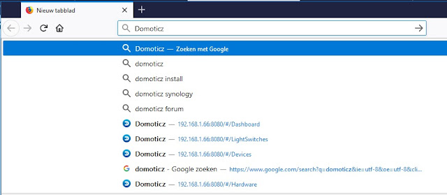
Normally you will know the IP number Domoticz has in your network. You can type Domoticz in your webbrowser (I am using Firefox) and the IP adress will show up.
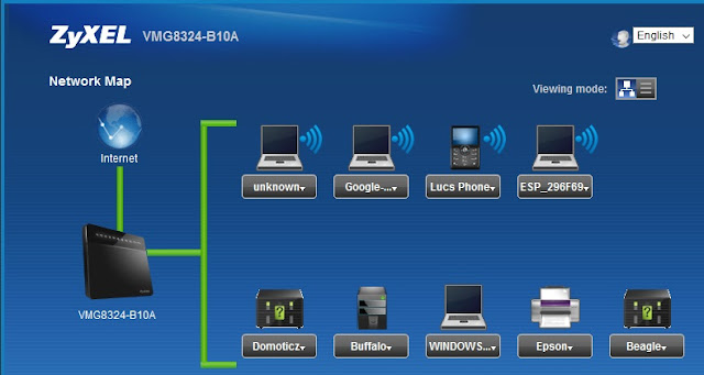
You can also open the webpage of your router (mine is a Zyxell) and there you can find the information.
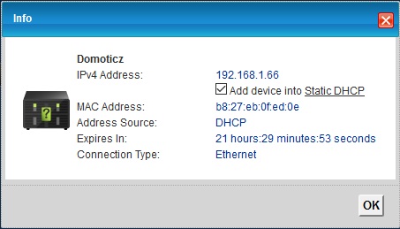
As you can see Domoticz is located at IP adress 192.168.1.66 in my case.
Look for the IP adress in your own system and write it down as we will need it in the program.
Finding the IDX of the switch.
The next step is to find the IDX number of the switch we are going to control.
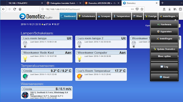
Open the Domoticz Dashboard and on the top left tab entry click on settings (instellingen in Dutch).
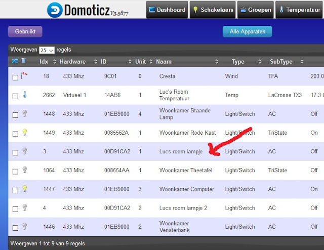
Click on devices and choose to diplay only the used devices. Above you can see part of the screen and the arrow points at the lamp we are going to control : Lucs room lampje. The lamp has the IDX number 3 as you can see at the beginning of the line.
Now we have all the information we need.
The first test.
PLEASE USE THIS PROGRAM WITH A LMAP IN YOUR HOBBYROOM/MANCAVE AND TRY NOT TO ANNOY YOUR SPOUSE / KIDS / ROOM-MATE !!
The first test is just a simple program that switches the lamp ON, waits 20 seconds, and switches it OFF again. This is the basic principle for controling Domoticz.
Do not set the delay shorter as 20 seconds. If you do the lamp will switch ON and OFF but Domoticz will not be able to react fast enough so status of the lamp will not be displayed on its dashboard.
#include <ESP8266WiFi.h>
#include <ESP8266HTTPClient.h>
// WiFi settings
#define wifi_ssid "ROUTERNAME"
#define wifi_password "PASSWORD"
// HTTP Domoticz settings
const char* host = "192.168.1.66";
const int port = 8080;
HTTPClient http;
int toggle = 0;
void setup() {
Serial.begin(115200);
setup_wifi();
}
void switchonoff(){
// Here is the Json format that Domoticz expects
// /json.htm?type=command¶m=switchlight&idx=99&switchcmd=On
String url = "/json.htm?type=command¶m=switchlight&idx=";
url += String(3);
toggle= 1 - toggle;
if (toggle==0){
url += "&switchcmd=Off";
}
else
{
url += "&switchcmd=On";
}
sendToDomoticz(url);
}
void loop() {
switchonoff();
delay (20000);
}
//Connect to wifi
void setup_wifi() {
delay(10);
Serial.println();
Serial.print("Connecting to ");
Serial.println(wifi_ssid);
WiFi.begin(wifi_ssid, wifi_password);
while (WiFi.status() != WL_CONNECTED) {
delay(500);
Serial.print(".");
}
Serial.println("");
Serial.println("WiFi connection Established");
Serial.print("IP Adress : ");
Serial.print(WiFi.localIP());
}
void sendToDomoticz(String url){
Serial.print("Connecting to ");
Serial.println(host);
Serial.print("Requesting URL: ");
Serial.println(url);
http.begin(host,port,url);
int httpCode = http.GET();
if (httpCode) {
if (httpCode == 200) {
String payload = http.getString();
Serial.println("Domoticz response ");
Serial.println(payload);
}
}
Serial.println("closing connection");
http.end();
}
We'll go over the program step by step.
#include <ESP8266WiFi.h>
#include <ESP8266HTTPClient.h>
We need to include these two libraries to communicate over HTTP.
// WiFi settings
#define wifi_ssid "ROUTERNAME"
#define wifi_password "PASSWORD"
// HTTP Domoticz settings
const char* host = "192.168.1.66";
const int port = 8080;
Here the settings are defined which gives our program the information it needs to communicatie with your router and Domoticz. Make sure you fill in your own credentials for the ROUTERNAME and PASSWORD and replace the IP number for Domoticz with the number you found as described earlier.
HTTPClient http;
int toggle = 0;
An instance is created for the HTTPClient library called simply http. and a variable is created called toggle which will switch the light from ON to OFF.
void switchonoff(){
// Here is the Json format that Domoticz expects
// /json.htm?type=command¶m=switchlight&idx=99&switchcmd=On
String url = "/json.htm?type=command¶m=switchlight&idx=";
url += String(3);
toggle= 1 - toggle;
if (toggle==0){
url += "&switchcmd=Off";
}
else
{
url += "&switchcmd=On";
}
sendToDomoticz(url);
}
Remember the code we found in the documentation:
http://192.168.1.2:8080//json.htm?type=command¶m=switchlight&idx=99&switchcmd=On
The code above only builds the JSON part.
url += String(3);
Fill in the IDX you found for your lamp as described before in this article.
sendToDomoticz(url);
When the URL is build we call the routine that actually sends it to Domoticz.
void sendToDomoticz(String url){
Serial.print("Connecting to ");
Serial.println(host);
Serial.print("Requesting URL: ");
Serial.println(url);
http.begin(host,port,url);
int httpCode = http.GET();
if (httpCode) {
if (httpCode == 200) {
String payload = http.getString();
Serial.println("Domoticz response ");
Serial.println(payload);
}
}
Serial.println("closing connection");
http.end();
}
In this routine there is a lot of debug information printed to the serial port so you can see if everythingb goes well. There is however just one line that is really important:
http.begin(host,port,url);
This line sends the build URL to the host (IP number of Domoticz, previous defined) and port number.
The next lines check what Domoticz sends back and displays that on the serial monitor.
Run the program.
Domoticz Dashboard
Open the Domoticz Dashboard and look at the selected switch.
As you can see the lamp will switch on and 20 seconds later it will switch off again. As you can check the lamp itself you can also see this happening at the Domoticz Dashboard. Although it will take several seconds for the Dashboard to react. That is why the delay of minimal 20 seconds is so important in the program.
More next time.
Till then experiment for yourself.
Have fun
Luc Volders


